917
Pellet-fired decentralized power generation
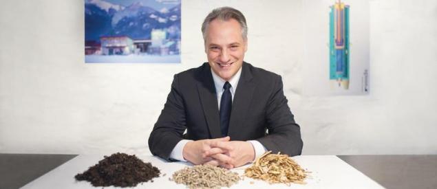
In January 2015, the German joint-stock company ENTRADE Energiesysteme AG, presented his block mobile thermal power plant (TPP) E3, which is the technology of gasification of wood pellets. Six-cylinder four-stroke gas internal combustion engine (engine operating on the Otto cycle, the so-called Otto-motor), running on generator gas (synthesis gas) obtained at the outlet from the reactor-gasifier, complete with a three-phase generator allows to 25 kW•h of electricity with a voltage of 400 V, are additionally generated 55 kWh of thermal energy that can be used for heating of buildings.
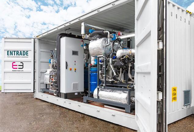
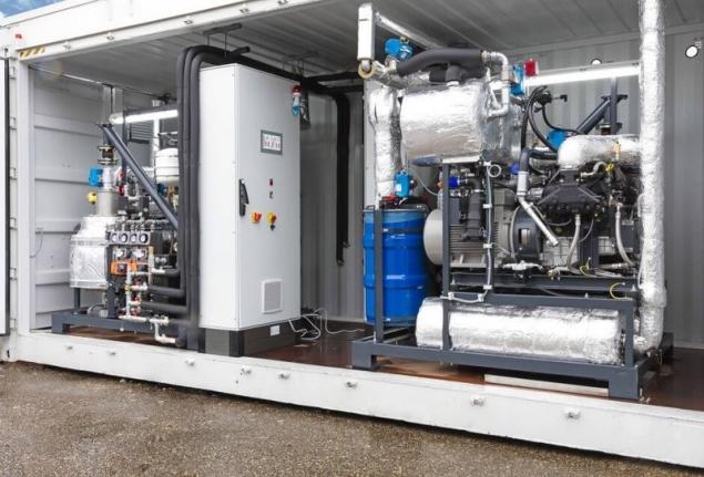
In Germany the TPP can fully provide heat and electricity 15-room apartment house. Overall efficiency of the plant is 85% (24% for electricity and 61% heat). Such small-sized gas thermal power plant (160х190х200 cm), consisting of two separate units — gas generator and unit with a gas motor and an electric generator, never before used for commercial purposes.
Both units are mounted on a separate frame in the frame designs and easily loaded and unloaded with the help of an ordinary loader and in case of his absence with the loading and unloading can be very good five or six porters.
Station size allow easily to make it into the building through almost any door. To place both units are connected, additionally connects them to the control Board, and thermal power plants are ready to start work. It is desirable to equip the pellet storage auto feed pellets. But in the absence of such possibility it is possible to store pellets in any closed room in big bags or in small packaging (bags of 10 or 15 kg) and having to manually fill them into feed hopper of power plants.
The station is at full load consumes 22 kg of pellets per hour, i.e. 1 kg of pellets to generate a little more than 1 kWh of electricity and 2.5 kWh heat. Despite the fact that the manual spelled out the station to use wood pellets standard ENplus A1 6 mm, it is possible to use industrial or pellets standard ENplus class In 6 mm or 8 mm, that is, for the EU, with ash content up to 1.5%.
You can use pellets with a higher ash content, but will often have to remove the ashes from the ash pan. TPP operates in a fully automatic mode and meets all European safety standards. The geometry of the high temperature of the reactor air supply to the combustion zone and much more were modeled using the latest computer technology. The reactor operates on the principle of gasification in the dense layer.
A peculiarity of the reactor — gasifier TPP E3 is the cylindrical form of the neck (the other manufacturers of the similar equipment made exclusively to the neck of the conical shape).
Also, the developers of TES brought in the design to minimize the moving and rotating parts (such details are only in the node of feed pellet and the motor generator), thereby ensuring a high reliability of the whole station. In the area of the gas generation no injectors or nozzles. In the reactor chamber simultaneously occur three process (endothermic and exothermic): pyrolysis, partial combustion and oxidation of the solid fuel. Their combination can describe the following chemical formulas:
C + O2 → CO2
2H2 + O2 → 2Н2О
with the release of thermal energy,
C + CO2 → 2СО
C + H2O → CO + H2
with the consumption of thermal energy.
When gasification of solid fuel, in this case wood pellets, in the gas phase goes up to 80% of the organic part of the fuel. Because of insensitivity to the quality of raw materials and mineral impurities and moisture, the method of gasification is widely used in the processing of low-grade fuels that can be used on gas power plants. In addition, when burning get the so-called producer gas (or synthesis gas) are allocated significantly less harmful substances than in the direct combustion of solid fuel (pellets).
In addition, when the reverse process of gasification is provided by the minimal content in the synthesis gas resins, because the gas resulting from decomposition of the fuel passes through the high temperature zone of oxidation, which leads to almost complete decomposition. In the first experimental samples of TPP E3 content generated from the gas generating resin in 1 m3 of synthesis gas was 0.12-0.15 g, and in serial samples only 0.05 g/m3.
This result was achieved including due to the special geometry of the combustion chamber of the reactor, which emphasizes Director and Chairman of the Board of Entrade Energiesysteme AG Julien I. High quality synthesis gas provides a long-lasting uniform effect on the fuel (pellets) high temperature: to 1200°C. the resulting synthesis gas 25% carbon monoxide, 18% hydrogen, 2% methane and non-combustible nitrogen in the residue.
Unlike TPP E3, in other similar gas generator is used the non-homogeneous, i.e. heterogeneous fuel (for example, chips of different fractions), which is exposed to a temperature below 1200°C. in addition, installations of other manufacturers different design and geometry of the combustion chamber of the reactor, etc., and in the process of gasification of fuel produces significantly more tar than when using TPP E3. At a constant daily work increased skaloobraznuju leads to slagging of the working surfaces of the reactor and a considerable reduction in the efficiency of thermal power plants, and in some cases to its stop and damage or even accidents.
TPP E3 is equipped with a cyclone and the cheap paper filter, which is reliable in operation and easily replaced.
The marketing objective of the company ENTRADE Energiesysteme AG, according to its management, are mainly emerging markets and third world countries, where such block-type thermal power station, as E3, can replace diesel generators that currently are major and in most cases the only source of electricity in the absence of centralized power. Due to this replacement can significantly reduce fuel costs and to reduce the cost of electricity generation, not to mention the possibility of obtaining thermal energy, and in the Equatorial and tropical regions and cold (technology absorption — trigeneration).
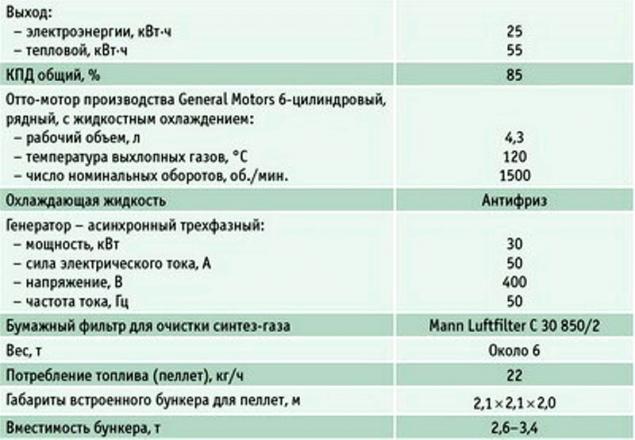
Table 1. The main technical features of the mini-TES E3
Block mini-TES E3 can be maximum 24 hours delivered transport aircraft anywhere in the world. The advantages of the design of such a thermal power plant include the simplicity and reliability. On the equipment to ensure the operation and control of installed a total of 12 sensors. For comparison, the gas thermal power plant production Agnion energy GmbH with the capacity of 400 kW·h of electricity with patented Heatpipe Reformer gas generator 3000 installed sensors. Another advantage of the construction of TPP E3 is manning the station, a reliable gas engine manufacturing concern General Motors.
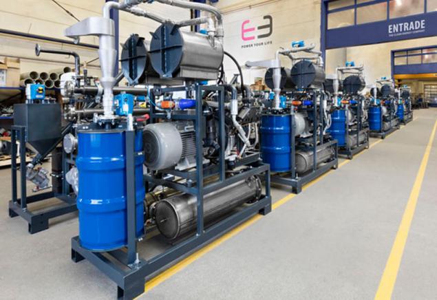
The first seven serial mini-TES E3 was established in 2015 in Germany, the UK, Austria and the USA. 13 such stations were commissioned at the end of the same year in Italy and Switzerland. In Germany through the use of TPP E3 in pilot projects in apartment buildings managed to reduce electricity tariff up to 40% compared with the previous.
In addition, mini-TES was installed in one of the villages of Uganda (East Africa) and provides its residents with the necessary energy. As fuel at this station was experimentally used bamboo, and was received a positive result. This project is funded by the world Bank. For operational management and maintenance of the project and other projects planned for implementation on the African continent, was registered a subsidiary of Entrade Africa Growth.
Today for Entrade Energiesysteme AG, according to its Director, one of the priorities is obtaining an increasing number of references from objects where already installed and working mini-TES E3. In the development of gasification technology company for eight years, has invested 51 million euros.
Most of the project research was conducted at the research centre of the Technical University of Graz, where employees of Entrade for 18 months was engaged in the development of TPP E3 and registered during this time, 14 patents for know-how. Now the employees in this center are testing a new development: 45-kilowatt mini-power plants. The task is to put all the equipment in the station of the same size as E3. For a new TPP the company Entrade has already received a number of pre-orders. That is the strategy of the company — expanding lineup of unified gas generator mini-TES. By the way, before the development of a 45-kilowatt model applications for thermal power plant with the capacity of 25 kW were realized by combining several individual units in one module container type: two in one (2x25 kW) or four-in-one (4x25 kW).
Mini-TES E3 is mounted in a 20-foot container 6,058х2,438х2,896 m; for installation of the container is 15 m2. In this container you can place the two units and to the output 50 kW•h of electric and 110 kWh of thermal energy; a 40-foot container to fit four of the gas generator, which allows you to output 100 kW•h of electricity and 220 kWh of heat. Management is completely automatic, on the connection, and start up takes about two hours. The cost of a single mini-TES E3 in container design — 125 thousand Euro)/ex works.
Competitors are not asleepFirm Burkhardt GmbH manufactures gas block mini-TES for 10 years. In 2013, the pipeline Assembly shops of the company has gone one hundredth gas power station. In the reference list of company are entered more than 120 biomass (chips and pellets) gas mini thermal power station both in European and in other countries. In recent years the company has concentrated on the use of their stations as fuel pellets exclusively.
The owner and Director of the company Gerhard BURKHARDT believes that the use of pellets in the gas generating significantly more efficient than chips. The calorific value of pellets is almost three times higher pellets are uniform in size, and space for storage and transportation demand significantly less than chips, and the process of gasification is much better.
Feed pellet, in contrast to the flow of wood chips, fully automated, no need to use the fuel stock of wheel mini loader, maintenance costs for gas-pellet mini-TES below. Now the company produces pellet gas mini thermal power station BHKW ECO 165 ECO BHKW HG and 180 HG.
Main differences: the first is equipped with Otto-motor production company MAN and the second liquid-gas engine operating on dual fuel (gas-air mixture with the addition of a small volume of liquid, the so-called pilot fuel injection into the cylinders which provides increased power and engine efficiency). If the motor MAN can work only on a wood generator gas tank of the second engine without any adjustments, it is possible for a short time in case of force majeure (failure, repair gas block or, for example, the lack of pellets) pour any liquid fuels: diesel, biodiesel, canola oil, etc for its smooth operation on wood gas needs a constant flow of pilot liquid fuel.
Pros BHKW ECO 165 HG: its motor does not require ignition of liquid fuel, lower emission of harmful substances. BHKW ECO 165 HG generate 165 kWh of electricity and 260 kWh of heat per hour consumes 110 kg of pellets. BHKW ECO 180 HG generates 180 kWh of electricity and 280 kWh of heat and also consumes per hour of pellets 110 kg plus 4 l of rapeseed oil as pilot fuel.
Last year, the leadership of the company Burkhardt has set its engineers the task to quickly develop and prepare all technical documentation for serial production of pellet gas mini CHP 50 kW•h. Why is there such a need?
Based on the latest additions and changes to the law on renewable energy sources cogeneration plant with electricity generation of more than 50 kWh using biomass as fuel, are not covered by subsidies, that is, the government absolved itself of the obligation to pay for "green" energy for higher prices in its submission to the mains. Therefore, the owners of thermal power plant capacity of over 50 kWh can now use the power generated and heat exclusively for their own needs or sell it to neighboring consumers. And if for many years thermal power plant with capacity more than 50 kW·h was quite profitable even if the non-use or partial use of heat is mainly due to the guaranteed sale of electricity to the grid, but now the situation has changed dramatically.
Therefore, manufacturers of biofuel mini-power station rely on station power to 50 kW•h (for example — products manufacturer Entrade).
It should be noted that gasifiers of the company Burkhardt work on a large gasification CHP plant using wood pellets as fuel. Interesting story of this project: on one of the largest in the EU oil extraction plant oil extraction plant "gold mill" in Ladbergen (Germany), which produces over 90 tonnes per year of vegetable oil, in the framework of the project energy Park "Golden energy" together with its strategic partner MEZ — local energy company Energy Muensterland GmbH in 2008 had been installed 10 block fuel oil power plants with a capacity of 430 kWh, working on palm oil.
But when the price per ton of palm oil increased from 400 to 1100 euros, in September 2008 management of the "Golden mill" in the beginning was replaced by liquid fuel power plant 12 mini-TES production companies Burkhardt, and then brought the number to thirty-two. Their total capacity of thermal power is 10.2 MW and electricity capacity of 7.72 MW (including one block of the gas power station of 1 MW, which is used in an emergency and ensures the efficient operation of the entire thermal power plants during peak loads, and at the time of conclusion of work for the repair or maintenance of blocks of thermal power plants working on pellets).
To be used as fuel pellets, the bulk of which is shipped by road and the rest — river vessels through the canal Dortmund-EMS (pier is a few hundred metres from MEZ).
The annual consumption of pellet thermal power plant is 30 thousand tons To generate 1 kWh of electricity consumed 500-600 g of pellets. Serve the whole station 11 specialists of the company Burkhardt. In 2009, was extended heating network with a length of 5.5 km from the airport münster-osnabrück, and now cheap thermal energy for heating and hot water is going directly to the airport terminals. In addition, due to tri-generation in summer in terminal 2 of the airport cooled with air conditioning. In the year the airport consumes about 5,000 kWh of thermal energy.
India evaluated the ability of the gas generation
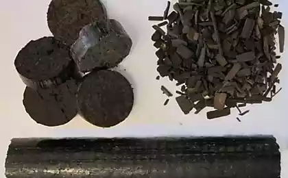
Experts in the field of gas generation always emphasize that great progress in the use of biomass for this process reached India company. They have long been serially produced gas generator of TES in a wide power range, in which fuel is basically a waste of agricultural industry (rice chaff, sunflower husks, straw, etc.), as well as wood fuel in the form of chips, briquettes and pellets.
We consider in detail the gasification plant of Indian manufacture with Chinese gas motor that generate 120 kWh of electricity. For obtaining clean producer gas from biomass (pellets) in this design uses the inverted type gas generator with fixed bed and open top for access to the limited volume of air. Inside the gasifier the biomass as it moves downwards through the zones of drying, pyrolysis, combustion, and recovery turns into a hot producer gas and ash.
Thanks to facing the principle of gasification of pyrolysis tars which are separated in the pyrolysis zone, almost completely burn inside the inflator, and the gas exiting the gasifier contains only small amounts of tars and water in the vapor phase and fine particles of coal and ash which are removed in the gas purification system. Biomass suitable for gasification in gas generators of the inverted type with fixed bed and an open top, shall meet the following requirements: humidity is — no more than 12%, particle size > 2 mm proportion of particles larger than 2 mm and less than 3 mm — not more than 10%, the melting point of the ash — not less than 1100°C) bulk density not less than 100 kg/m3. Pellets fully meet these criteria, but as fuel you can use wood chips, if you slightly change the site of injection.
Gas power plant consists of several sections. Plot fuel is used to supply pellets to the gasifier. The delivery system includes a hopper for storing pellets with bottom discharge device in a receiving tray of a vertical bucket conveyor that lifts the pellets in the hopper of the gasifier. Feed pellet can also be upper conveyor directly into the receiving hopper of the gasifier.
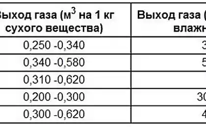
Table 2. Specifications gas
installation model FBG-200 (India)
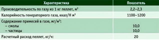
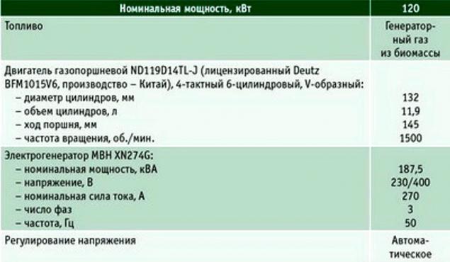
Table 3. Technical specifications of generating sets
installation
To obtain pellets of a clean gas generator for the gasification area there is a gas plant FBG-200, consisting of gas generator and system of dry cleaning and cooling of producer gas. The installation of the FBG, which are serially produced at the plant, certified by CE, ISO 9001, ISO 14001 and OHSAS 18001, are used in several hundred sites around the world for gasification of rice husk and sunflower, wood chips and pellets.
Cleaned generator gas is fed to the area of power generation, where the receiving of the gas generator of electrical energy installed electrical generating equipment with capacity 100-120 kW. It is composed of: line feed generator gas engine, gas engine operating on generator gas, generator and control Cabinet. In the next section is the utilization of condensate produced during the cooling of the generator gas in the three-stage gas cooling system.
The gas generator consists of the following parts: the admission funnel, hopper of the gasifier reactor the gasifier with a sloping bottom on supports, screw conveyor for removing ash residue from the reactor) and the bucket conveyor (if required). The housing of the gas generator consists of two detachable parts. The upper part, called the bunker, is made of carbon steel and is a vessel of a conical shape, the top of which is mounted a locking device. In the bunker flow drying, pyrolysis (in which the biofuel is converted into charcoal with the emission of volatile products) and burning part of the volatile and charcoal.
In use, the hopper is removed from a crane for inspection of the lattice of the reactor, scraper, cleaning or changing of a cone burning, etc. the Hopper is mounted vertically and coaxially with the cone of the combustion reactor. Detachable connection of the hopper and the cone of combustion, is inserted from above and coaxially to the reactor, sealed with an asbestos or ceramic cord. The flanges of the hopper and the reactor are fixed by bolts. The lower part, called the reactor, is made of stainless steel and is a cylindrical vessel.
In the reactor are the reduction reaction and formed the gas generator. A large part of the pyrolysis tar, formed during pyrolysis are burned in the bunker and on the layer of hot charcoal, so that the gas emerging from the gas generator, and a low resin content. Hot charcoal with a small amount of ash removed from the gasifier by dry method through the flange in the lower part of the inclined bottom of the reactor and further screw conveyor with water cooling and two gate valves. Hot gas at a temperature of 350-400°C is taken from the reactor of the gas generator through the outlet through the vacuum that is created by the main circulator, and further trained in multistage system of dry cleaning and cooling.
The original system dry cleaning and cooling of gas allows to obtain pure, containing not more than 10 mg/м3пиролизных resins and particulate producer gas, whose temperature is about 25°C, without the use of water and generate large amount of wastewater contaminated with tar and particles of combustion. In the cooling process of gas is formed from 100 to 140 ml of the condensate per 1 kg of fuel delivered to the gas generator (the exact output of the condensation depends on the humidity of pellets).
The condensate is recycled. Dry cleaning and cooling of the gas occurring in the starting circulator with a combustion chamber through which the initial gas with excess tar during the first 5-10 minutes after ignition of the gas generator is vented to the atmosphere, and then for a further 50-70 min. burned at the flare. Such operation helps prevent clogging of pipelines and filters gas located on.
Rough cleaning of gas from particles of charcoal runs in the cyclone and the original high temperature gas filter reverse purge with nitrogen. The particles of charcoal deposited on the surface of the filter elements of a scrubber, high porosity, and these pores absorb a pair of heavy pyrolysis tar.
The accumulation of particles on the surface of the differential pressure across the filter elements increases and when it reaches a certain threshold this layer are reset to the receiver by a series of reverse pulses of compressed nitrogen gas.
After a rough cleaning of the gas is cooled to a temperature of about 25°C or below in a heat exchanger of the first stage, cooled by water from a cooling tower of the gas generator, and heat exchangers of the second and third stages, the cooled water from the chiller. In the process of cooling to a low temperature of the pair of light pyrolysis tar and water contensious and is discharged to the land disposal of condensate.
Fine purification of gas occurs in the air dryer with a filler of wood chips and two bed filters filled with dry sawdust with a fraction of 2-3 mm. the Main circulator selects the gas from the reactor of the gas generator creates a gas flow through the entire system and delivers the gas in a pressure tank automatic flare. From the pressure tank, the gas is supplied to the control filter with a replaceable synthetic filter cartridges and further to a gas manifold, where it turns out the supply line of gas engine electric generating sets. Flare unit serves for the discharge of gas through the main drain and the candle standing on the roof of the building gas station during on and off of the generator.
Flare unit consists of a pressure tank, the main candle, equipped with blamedisplayitem, pneumatic shut-off valve, manual valve or Electromechanical valve device for automatic spark ignition of gas at the top of the main candle, the candle of the drainage for discharge of residual gas in a closed home the glow plug and test the spark to determine the quality of gas when you turn on the inflator. After ignition of the gas generator, and a clean gas discharge through the main candle is blocked, and the gas enters the manifold from which is directed through pipelines to the gas piston engine.
Control of gas generator is carried out using the remote control automatic control with the CPU Siemens CPU 313C-2 DP or similar that allows you to track all your important system settings that turn on and off discrete equipment, and to ensure the performance of the gas generator in accordance with output load power generators in automatic mode. Visual control parameters of the gasification process is carried out on the display Siemens TP-177 A. the basis of "filling" the control Cabinet, which is a programmable device for controlling the engine and generator, SmartGen controller (Germany).
The engine of the electric generator is cooled by a remote radiator (dry cooling tower), which is composed of the high temperature cooling circuit of the external engine and the low-temperature circuit charge-air cooler. For additional heat generation can be installed in block-modular heat recovery system of the engine, which you can use to get another 150-200 kW of heat.
The condensate that forms when cooling the gas, is a dark brown liquid with a strong phenolic smell and high concentration of dissolved organic substances and ammonium and a high pH (>9), biochemical oxygen demand and chemical oxygen demand. The condensate, it is recommended to accumulate and dispose of. Disposal of condensate can be carried out in the evaporator. The condensate from the collection tank is pumped to the evaporator, the spray nozzle sprays it in the form of tiny droplets towards the hot stream of flue gases generated by the burner in which is burned a small amount of gas from the gas generator (for evaporation of 1 kg of condensate is required 0,9-1,0 N m3 of gas). All impurities by momentary heating to a high temperature collapse, the condensate evaporates, and the output from the evaporator the content of harmful substances in flue gases emitted into the atmosphere, does not exceed the established norms.
The removal of ash and charcoal — dry, through the gateway device.
Equipment, supply, engineering, erection supervision and commissioning of the stations is performed by a company from the UK. The cost of such plants is $230 million, that is more than two times lower than the cost of equivalent German power stations. But if we exclude the services of the British, to import key components or accessories directly from the manufacturer, to involve Russian, Indian or Chinese engineering company, the total cost of delivery and commissioning of thermal power plant can be reduced more.
Even today, despite the significant devaluation of the ruble, the German mini-gas thermal power plant can pay for itself in Russia for two or three years, decentralized power generation of the North, Siberia and the Far East, as electricity tariffs in most of these regions exceed 40 RUB./ kW•h, and often reach 100 RUB./ kW•h. unfortunately, almost all Russian development of gas thermal power plants operating on solid fuel, due to many objective and subjective reasons, on experimental samples has not moved. published
P. S. And remember, only by changing their consumption — together we change the world! ©
Join us in Facebook , Vkontakte, Odnoklassniki
Source: lesprominform.ru/jarchive/articles/itemshow/4340

In Germany the TPP can fully provide heat and electricity 15-room apartment house. Overall efficiency of the plant is 85% (24% for electricity and 61% heat). Such small-sized gas thermal power plant (160х190х200 cm), consisting of two separate units — gas generator and unit with a gas motor and an electric generator, never before used for commercial purposes.
Both units are mounted on a separate frame in the frame designs and easily loaded and unloaded with the help of an ordinary loader and in case of his absence with the loading and unloading can be very good five or six porters.
Station size allow easily to make it into the building through almost any door. To place both units are connected, additionally connects them to the control Board, and thermal power plants are ready to start work. It is desirable to equip the pellet storage auto feed pellets. But in the absence of such possibility it is possible to store pellets in any closed room in big bags or in small packaging (bags of 10 or 15 kg) and having to manually fill them into feed hopper of power plants.

The station is at full load consumes 22 kg of pellets per hour, i.e. 1 kg of pellets to generate a little more than 1 kWh of electricity and 2.5 kWh heat. Despite the fact that the manual spelled out the station to use wood pellets standard ENplus A1 6 mm, it is possible to use industrial or pellets standard ENplus class In 6 mm or 8 mm, that is, for the EU, with ash content up to 1.5%.
You can use pellets with a higher ash content, but will often have to remove the ashes from the ash pan. TPP operates in a fully automatic mode and meets all European safety standards. The geometry of the high temperature of the reactor air supply to the combustion zone and much more were modeled using the latest computer technology. The reactor operates on the principle of gasification in the dense layer.
A peculiarity of the reactor — gasifier TPP E3 is the cylindrical form of the neck (the other manufacturers of the similar equipment made exclusively to the neck of the conical shape).

Also, the developers of TES brought in the design to minimize the moving and rotating parts (such details are only in the node of feed pellet and the motor generator), thereby ensuring a high reliability of the whole station. In the area of the gas generation no injectors or nozzles. In the reactor chamber simultaneously occur three process (endothermic and exothermic): pyrolysis, partial combustion and oxidation of the solid fuel. Their combination can describe the following chemical formulas:
C + O2 → CO2
2H2 + O2 → 2Н2О
with the release of thermal energy,
C + CO2 → 2СО
C + H2O → CO + H2
with the consumption of thermal energy.
When gasification of solid fuel, in this case wood pellets, in the gas phase goes up to 80% of the organic part of the fuel. Because of insensitivity to the quality of raw materials and mineral impurities and moisture, the method of gasification is widely used in the processing of low-grade fuels that can be used on gas power plants. In addition, when burning get the so-called producer gas (or synthesis gas) are allocated significantly less harmful substances than in the direct combustion of solid fuel (pellets).
In addition, when the reverse process of gasification is provided by the minimal content in the synthesis gas resins, because the gas resulting from decomposition of the fuel passes through the high temperature zone of oxidation, which leads to almost complete decomposition. In the first experimental samples of TPP E3 content generated from the gas generating resin in 1 m3 of synthesis gas was 0.12-0.15 g, and in serial samples only 0.05 g/m3.
This result was achieved including due to the special geometry of the combustion chamber of the reactor, which emphasizes Director and Chairman of the Board of Entrade Energiesysteme AG Julien I. High quality synthesis gas provides a long-lasting uniform effect on the fuel (pellets) high temperature: to 1200°C. the resulting synthesis gas 25% carbon monoxide, 18% hydrogen, 2% methane and non-combustible nitrogen in the residue.
Unlike TPP E3, in other similar gas generator is used the non-homogeneous, i.e. heterogeneous fuel (for example, chips of different fractions), which is exposed to a temperature below 1200°C. in addition, installations of other manufacturers different design and geometry of the combustion chamber of the reactor, etc., and in the process of gasification of fuel produces significantly more tar than when using TPP E3. At a constant daily work increased skaloobraznuju leads to slagging of the working surfaces of the reactor and a considerable reduction in the efficiency of thermal power plants, and in some cases to its stop and damage or even accidents.
TPP E3 is equipped with a cyclone and the cheap paper filter, which is reliable in operation and easily replaced.

The marketing objective of the company ENTRADE Energiesysteme AG, according to its management, are mainly emerging markets and third world countries, where such block-type thermal power station, as E3, can replace diesel generators that currently are major and in most cases the only source of electricity in the absence of centralized power. Due to this replacement can significantly reduce fuel costs and to reduce the cost of electricity generation, not to mention the possibility of obtaining thermal energy, and in the Equatorial and tropical regions and cold (technology absorption — trigeneration).
Table 1. The main technical features of the mini-TES E3

Block mini-TES E3 can be maximum 24 hours delivered transport aircraft anywhere in the world. The advantages of the design of such a thermal power plant include the simplicity and reliability. On the equipment to ensure the operation and control of installed a total of 12 sensors. For comparison, the gas thermal power plant production Agnion energy GmbH with the capacity of 400 kW·h of electricity with patented Heatpipe Reformer gas generator 3000 installed sensors. Another advantage of the construction of TPP E3 is manning the station, a reliable gas engine manufacturing concern General Motors.
The first seven serial mini-TES E3 was established in 2015 in Germany, the UK, Austria and the USA. 13 such stations were commissioned at the end of the same year in Italy and Switzerland. In Germany through the use of TPP E3 in pilot projects in apartment buildings managed to reduce electricity tariff up to 40% compared with the previous.
In addition, mini-TES was installed in one of the villages of Uganda (East Africa) and provides its residents with the necessary energy. As fuel at this station was experimentally used bamboo, and was received a positive result. This project is funded by the world Bank. For operational management and maintenance of the project and other projects planned for implementation on the African continent, was registered a subsidiary of Entrade Africa Growth.
Today for Entrade Energiesysteme AG, according to its Director, one of the priorities is obtaining an increasing number of references from objects where already installed and working mini-TES E3. In the development of gasification technology company for eight years, has invested 51 million euros.
Most of the project research was conducted at the research centre of the Technical University of Graz, where employees of Entrade for 18 months was engaged in the development of TPP E3 and registered during this time, 14 patents for know-how. Now the employees in this center are testing a new development: 45-kilowatt mini-power plants. The task is to put all the equipment in the station of the same size as E3. For a new TPP the company Entrade has already received a number of pre-orders. That is the strategy of the company — expanding lineup of unified gas generator mini-TES. By the way, before the development of a 45-kilowatt model applications for thermal power plant with the capacity of 25 kW were realized by combining several individual units in one module container type: two in one (2x25 kW) or four-in-one (4x25 kW).
Mini-TES E3 is mounted in a 20-foot container 6,058х2,438х2,896 m; for installation of the container is 15 m2. In this container you can place the two units and to the output 50 kW•h of electric and 110 kWh of thermal energy; a 40-foot container to fit four of the gas generator, which allows you to output 100 kW•h of electricity and 220 kWh of heat. Management is completely automatic, on the connection, and start up takes about two hours. The cost of a single mini-TES E3 in container design — 125 thousand Euro)/ex works.
Competitors are not asleepFirm Burkhardt GmbH manufactures gas block mini-TES for 10 years. In 2013, the pipeline Assembly shops of the company has gone one hundredth gas power station. In the reference list of company are entered more than 120 biomass (chips and pellets) gas mini thermal power station both in European and in other countries. In recent years the company has concentrated on the use of their stations as fuel pellets exclusively.
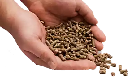
The owner and Director of the company Gerhard BURKHARDT believes that the use of pellets in the gas generating significantly more efficient than chips. The calorific value of pellets is almost three times higher pellets are uniform in size, and space for storage and transportation demand significantly less than chips, and the process of gasification is much better.
Feed pellet, in contrast to the flow of wood chips, fully automated, no need to use the fuel stock of wheel mini loader, maintenance costs for gas-pellet mini-TES below. Now the company produces pellet gas mini thermal power station BHKW ECO 165 ECO BHKW HG and 180 HG.
Main differences: the first is equipped with Otto-motor production company MAN and the second liquid-gas engine operating on dual fuel (gas-air mixture with the addition of a small volume of liquid, the so-called pilot fuel injection into the cylinders which provides increased power and engine efficiency). If the motor MAN can work only on a wood generator gas tank of the second engine without any adjustments, it is possible for a short time in case of force majeure (failure, repair gas block or, for example, the lack of pellets) pour any liquid fuels: diesel, biodiesel, canola oil, etc for its smooth operation on wood gas needs a constant flow of pilot liquid fuel.
Pros BHKW ECO 165 HG: its motor does not require ignition of liquid fuel, lower emission of harmful substances. BHKW ECO 165 HG generate 165 kWh of electricity and 260 kWh of heat per hour consumes 110 kg of pellets. BHKW ECO 180 HG generates 180 kWh of electricity and 280 kWh of heat and also consumes per hour of pellets 110 kg plus 4 l of rapeseed oil as pilot fuel.
Last year, the leadership of the company Burkhardt has set its engineers the task to quickly develop and prepare all technical documentation for serial production of pellet gas mini CHP 50 kW•h. Why is there such a need?
Based on the latest additions and changes to the law on renewable energy sources cogeneration plant with electricity generation of more than 50 kWh using biomass as fuel, are not covered by subsidies, that is, the government absolved itself of the obligation to pay for "green" energy for higher prices in its submission to the mains. Therefore, the owners of thermal power plant capacity of over 50 kWh can now use the power generated and heat exclusively for their own needs or sell it to neighboring consumers. And if for many years thermal power plant with capacity more than 50 kW·h was quite profitable even if the non-use or partial use of heat is mainly due to the guaranteed sale of electricity to the grid, but now the situation has changed dramatically.
Therefore, manufacturers of biofuel mini-power station rely on station power to 50 kW•h (for example — products manufacturer Entrade).
It should be noted that gasifiers of the company Burkhardt work on a large gasification CHP plant using wood pellets as fuel. Interesting story of this project: on one of the largest in the EU oil extraction plant oil extraction plant "gold mill" in Ladbergen (Germany), which produces over 90 tonnes per year of vegetable oil, in the framework of the project energy Park "Golden energy" together with its strategic partner MEZ — local energy company Energy Muensterland GmbH in 2008 had been installed 10 block fuel oil power plants with a capacity of 430 kWh, working on palm oil.
But when the price per ton of palm oil increased from 400 to 1100 euros, in September 2008 management of the "Golden mill" in the beginning was replaced by liquid fuel power plant 12 mini-TES production companies Burkhardt, and then brought the number to thirty-two. Their total capacity of thermal power is 10.2 MW and electricity capacity of 7.72 MW (including one block of the gas power station of 1 MW, which is used in an emergency and ensures the efficient operation of the entire thermal power plants during peak loads, and at the time of conclusion of work for the repair or maintenance of blocks of thermal power plants working on pellets).
To be used as fuel pellets, the bulk of which is shipped by road and the rest — river vessels through the canal Dortmund-EMS (pier is a few hundred metres from MEZ).
The annual consumption of pellet thermal power plant is 30 thousand tons To generate 1 kWh of electricity consumed 500-600 g of pellets. Serve the whole station 11 specialists of the company Burkhardt. In 2009, was extended heating network with a length of 5.5 km from the airport münster-osnabrück, and now cheap thermal energy for heating and hot water is going directly to the airport terminals. In addition, due to tri-generation in summer in terminal 2 of the airport cooled with air conditioning. In the year the airport consumes about 5,000 kWh of thermal energy.
India evaluated the ability of the gas generation
Experts in the field of gas generation always emphasize that great progress in the use of biomass for this process reached India company. They have long been serially produced gas generator of TES in a wide power range, in which fuel is basically a waste of agricultural industry (rice chaff, sunflower husks, straw, etc.), as well as wood fuel in the form of chips, briquettes and pellets.
We consider in detail the gasification plant of Indian manufacture with Chinese gas motor that generate 120 kWh of electricity. For obtaining clean producer gas from biomass (pellets) in this design uses the inverted type gas generator with fixed bed and open top for access to the limited volume of air. Inside the gasifier the biomass as it moves downwards through the zones of drying, pyrolysis, combustion, and recovery turns into a hot producer gas and ash.
Thanks to facing the principle of gasification of pyrolysis tars which are separated in the pyrolysis zone, almost completely burn inside the inflator, and the gas exiting the gasifier contains only small amounts of tars and water in the vapor phase and fine particles of coal and ash which are removed in the gas purification system. Biomass suitable for gasification in gas generators of the inverted type with fixed bed and an open top, shall meet the following requirements: humidity is — no more than 12%, particle size > 2 mm proportion of particles larger than 2 mm and less than 3 mm — not more than 10%, the melting point of the ash — not less than 1100°C) bulk density not less than 100 kg/m3. Pellets fully meet these criteria, but as fuel you can use wood chips, if you slightly change the site of injection.
Gas power plant consists of several sections. Plot fuel is used to supply pellets to the gasifier. The delivery system includes a hopper for storing pellets with bottom discharge device in a receiving tray of a vertical bucket conveyor that lifts the pellets in the hopper of the gasifier. Feed pellet can also be upper conveyor directly into the receiving hopper of the gasifier.
Table 2. Specifications gas
installation model FBG-200 (India)

Table 3. Technical specifications of generating sets
installation

To obtain pellets of a clean gas generator for the gasification area there is a gas plant FBG-200, consisting of gas generator and system of dry cleaning and cooling of producer gas. The installation of the FBG, which are serially produced at the plant, certified by CE, ISO 9001, ISO 14001 and OHSAS 18001, are used in several hundred sites around the world for gasification of rice husk and sunflower, wood chips and pellets.
Cleaned generator gas is fed to the area of power generation, where the receiving of the gas generator of electrical energy installed electrical generating equipment with capacity 100-120 kW. It is composed of: line feed generator gas engine, gas engine operating on generator gas, generator and control Cabinet. In the next section is the utilization of condensate produced during the cooling of the generator gas in the three-stage gas cooling system.
The gas generator consists of the following parts: the admission funnel, hopper of the gasifier reactor the gasifier with a sloping bottom on supports, screw conveyor for removing ash residue from the reactor) and the bucket conveyor (if required). The housing of the gas generator consists of two detachable parts. The upper part, called the bunker, is made of carbon steel and is a vessel of a conical shape, the top of which is mounted a locking device. In the bunker flow drying, pyrolysis (in which the biofuel is converted into charcoal with the emission of volatile products) and burning part of the volatile and charcoal.
In use, the hopper is removed from a crane for inspection of the lattice of the reactor, scraper, cleaning or changing of a cone burning, etc. the Hopper is mounted vertically and coaxially with the cone of the combustion reactor. Detachable connection of the hopper and the cone of combustion, is inserted from above and coaxially to the reactor, sealed with an asbestos or ceramic cord. The flanges of the hopper and the reactor are fixed by bolts. The lower part, called the reactor, is made of stainless steel and is a cylindrical vessel.
In the reactor are the reduction reaction and formed the gas generator. A large part of the pyrolysis tar, formed during pyrolysis are burned in the bunker and on the layer of hot charcoal, so that the gas emerging from the gas generator, and a low resin content. Hot charcoal with a small amount of ash removed from the gasifier by dry method through the flange in the lower part of the inclined bottom of the reactor and further screw conveyor with water cooling and two gate valves. Hot gas at a temperature of 350-400°C is taken from the reactor of the gas generator through the outlet through the vacuum that is created by the main circulator, and further trained in multistage system of dry cleaning and cooling.
The original system dry cleaning and cooling of gas allows to obtain pure, containing not more than 10 mg/м3пиролизных resins and particulate producer gas, whose temperature is about 25°C, without the use of water and generate large amount of wastewater contaminated with tar and particles of combustion. In the cooling process of gas is formed from 100 to 140 ml of the condensate per 1 kg of fuel delivered to the gas generator (the exact output of the condensation depends on the humidity of pellets).
The condensate is recycled. Dry cleaning and cooling of the gas occurring in the starting circulator with a combustion chamber through which the initial gas with excess tar during the first 5-10 minutes after ignition of the gas generator is vented to the atmosphere, and then for a further 50-70 min. burned at the flare. Such operation helps prevent clogging of pipelines and filters gas located on.
Rough cleaning of gas from particles of charcoal runs in the cyclone and the original high temperature gas filter reverse purge with nitrogen. The particles of charcoal deposited on the surface of the filter elements of a scrubber, high porosity, and these pores absorb a pair of heavy pyrolysis tar.
The accumulation of particles on the surface of the differential pressure across the filter elements increases and when it reaches a certain threshold this layer are reset to the receiver by a series of reverse pulses of compressed nitrogen gas.
After a rough cleaning of the gas is cooled to a temperature of about 25°C or below in a heat exchanger of the first stage, cooled by water from a cooling tower of the gas generator, and heat exchangers of the second and third stages, the cooled water from the chiller. In the process of cooling to a low temperature of the pair of light pyrolysis tar and water contensious and is discharged to the land disposal of condensate.
Fine purification of gas occurs in the air dryer with a filler of wood chips and two bed filters filled with dry sawdust with a fraction of 2-3 mm. the Main circulator selects the gas from the reactor of the gas generator creates a gas flow through the entire system and delivers the gas in a pressure tank automatic flare. From the pressure tank, the gas is supplied to the control filter with a replaceable synthetic filter cartridges and further to a gas manifold, where it turns out the supply line of gas engine electric generating sets. Flare unit serves for the discharge of gas through the main drain and the candle standing on the roof of the building gas station during on and off of the generator.
Flare unit consists of a pressure tank, the main candle, equipped with blamedisplayitem, pneumatic shut-off valve, manual valve or Electromechanical valve device for automatic spark ignition of gas at the top of the main candle, the candle of the drainage for discharge of residual gas in a closed home the glow plug and test the spark to determine the quality of gas when you turn on the inflator. After ignition of the gas generator, and a clean gas discharge through the main candle is blocked, and the gas enters the manifold from which is directed through pipelines to the gas piston engine.
Control of gas generator is carried out using the remote control automatic control with the CPU Siemens CPU 313C-2 DP or similar that allows you to track all your important system settings that turn on and off discrete equipment, and to ensure the performance of the gas generator in accordance with output load power generators in automatic mode. Visual control parameters of the gasification process is carried out on the display Siemens TP-177 A. the basis of "filling" the control Cabinet, which is a programmable device for controlling the engine and generator, SmartGen controller (Germany).
The engine of the electric generator is cooled by a remote radiator (dry cooling tower), which is composed of the high temperature cooling circuit of the external engine and the low-temperature circuit charge-air cooler. For additional heat generation can be installed in block-modular heat recovery system of the engine, which you can use to get another 150-200 kW of heat.
The condensate that forms when cooling the gas, is a dark brown liquid with a strong phenolic smell and high concentration of dissolved organic substances and ammonium and a high pH (>9), biochemical oxygen demand and chemical oxygen demand. The condensate, it is recommended to accumulate and dispose of. Disposal of condensate can be carried out in the evaporator. The condensate from the collection tank is pumped to the evaporator, the spray nozzle sprays it in the form of tiny droplets towards the hot stream of flue gases generated by the burner in which is burned a small amount of gas from the gas generator (for evaporation of 1 kg of condensate is required 0,9-1,0 N m3 of gas). All impurities by momentary heating to a high temperature collapse, the condensate evaporates, and the output from the evaporator the content of harmful substances in flue gases emitted into the atmosphere, does not exceed the established norms.
The removal of ash and charcoal — dry, through the gateway device.
Equipment, supply, engineering, erection supervision and commissioning of the stations is performed by a company from the UK. The cost of such plants is $230 million, that is more than two times lower than the cost of equivalent German power stations. But if we exclude the services of the British, to import key components or accessories directly from the manufacturer, to involve Russian, Indian or Chinese engineering company, the total cost of delivery and commissioning of thermal power plant can be reduced more.
Even today, despite the significant devaluation of the ruble, the German mini-gas thermal power plant can pay for itself in Russia for two or three years, decentralized power generation of the North, Siberia and the Far East, as electricity tariffs in most of these regions exceed 40 RUB./ kW•h, and often reach 100 RUB./ kW•h. unfortunately, almost all Russian development of gas thermal power plants operating on solid fuel, due to many objective and subjective reasons, on experimental samples has not moved. published
P. S. And remember, only by changing their consumption — together we change the world! ©
Join us in Facebook , Vkontakte, Odnoklassniki
Source: lesprominform.ru/jarchive/articles/itemshow/4340


UAZ has built a prototype of "the Patriot" with methane LPG
Tatiana Chernigovskaya: Language is created for thinking