3538
Astrotreker for two nights
After reading the article about amateur astronomers I set about trying to take pictures of the star with an ordinary camera without a telescope. Article suggested the idea about astrotrekery - devices to compensate for the rotation of the sky on long exposures.
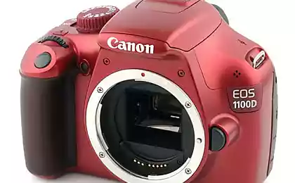
Googling, I discovered that they can be easily bought. But that's the price bites. For example, the cheapest Vixin Ploarie Star Tracker costs $ 400 + of Delivery. Yes and lifting his doubt. In the future, I planned to go from wide-angle lens and a 70-200 / 2.8 that came with the camera weighs under half kg.
In the search turned out that people do to themselves so called Barn Door Trackers: times , два and другие. Simply put - the door of the shed. The operating principle is simple - two boards connected by a canopy door. One of them is rotated at the same speed as the earth around its axis. The axis of the canopy always aim at Polaris. The bottom board is placed on a tripod and placed on the movable half tripod head with the camera.
Under the cut a lot of pictures.
I set about trying to make this tracker. Because without it you can only shoot stellar tracks of this type.

According to estimations for this almost everything was on hand. Decided to take as a basis this tracker . There you have a description of the methodology of calculation of the basic parameters.
The material has been selected for dostochek 10mm MDF as it was the experience of laser cutting in the studio. The material is cheap, easy to use. In terms of reliability far too early to say. Look at the trial operation.
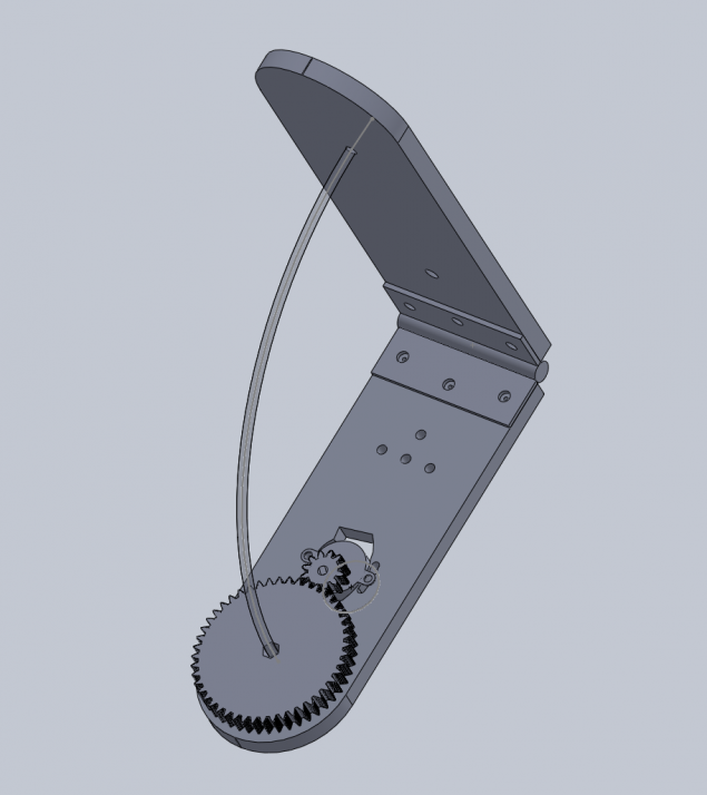
First, in the CAD-program I drew a model of what should have been done. To do this it was necessary to calculate the radius and rotational speed of the stud. By my estimation radius turned 182.85mm for M5 studs with 0.8mm thread pitch and speed nut 1 / min. Hairpin M5 was chosen as a compromise between strength and thread pitch.
Because subsequently wanted to shoot at 70-200 / 2.8 then had to count how many steps the motor to do in a minute that there were no blurring within a single pixel. After all I did prikidok tenfold margin for error that would not manufacture design dramatically worsened the situation.
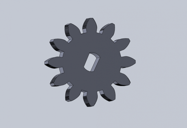
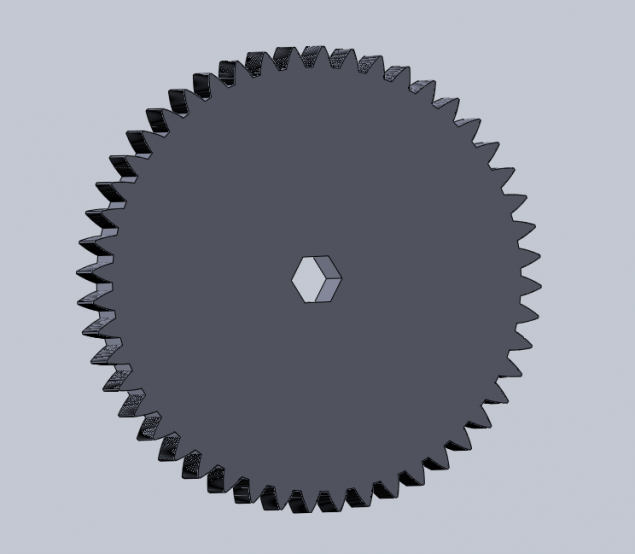
To rotate the nut on the stud in the original design of the gear used. But to find gear for adequate money and did not work. Tolna were on e-bay and then to $ 10 + delivery month. Therefore, the gears also decided to cut laser of MDF or acrylic.
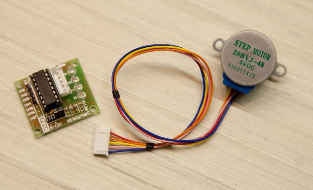
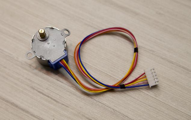
As stepper motor used Chinese 28BYJ-48. Their long I lay several pieces, all wanted to play. They stand with the card controller is less than $ 2 on ebay delivery. It is powered from 5-12 volts. Makes one revolution of the shaft of the 64 steps. It also has a gearbox with koefitsientom close to 63.68395: 1. Thus, the external axis is rotated in steps 2037 4-step mode or 4075-steps in the 8-step mode. Torque he is not great, but for this problem it is more than enough. On the Internet, write that turned out to get him on the order of 15 / min, but with an increase in power up to 12V. I decided that was enough for me 4 rev / min and made the gear ratio 4: 1 that would be for four turns of the engine nut on the stud makes one revolution.
In the store I bought a shed door with minimal backlash. Its size and width became dostochek. There's also bought a hairpin. In another shop scored fixings. On fasteners, cutting MDF, loop took about 100 USD. ($ 8.3). On ebay ordered a small ball head but so far has put the old conventional tripod.
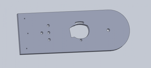
In the bottom half I made holes for attachment to a removable platform photo head Manfrotto 804RC2 whiling away I was. Also made the holes for the engine. I have provided a distance adjustment between gears by rotation around one of the motor mounting holes.
When I was pleased with the drawings, I took him to cut and brought here are wonderful but strong-smelling fumes details.
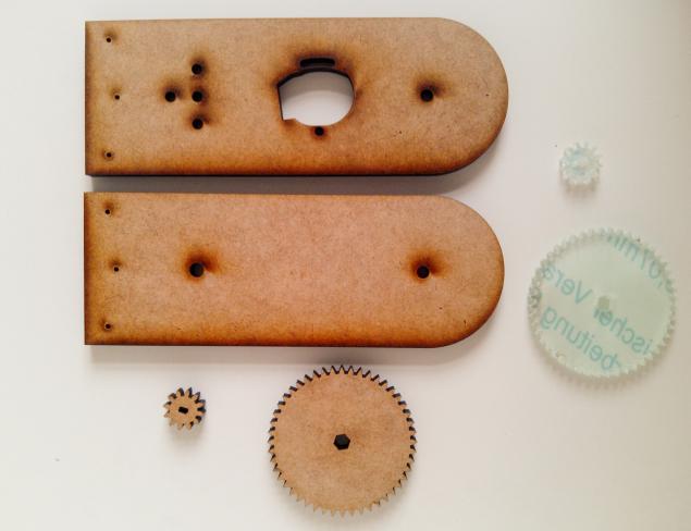
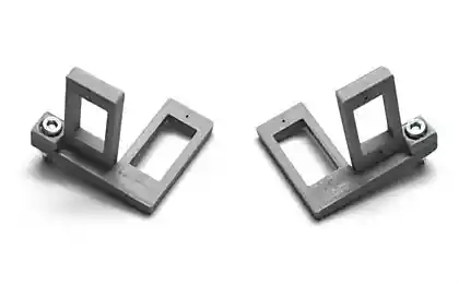
Gears and cut out of acrylic and MDF. With acrylic turned bad ends of the teeth poplavilis. I had to treat them with a file. Subjectively, in the course of MDF turned softer. But look on the battlefield.
Fixing the gear to the nut is very simple - a hole in the form of hexagon-tolerance. Acrylic - 8mm. Just put the 2 nuts M5.
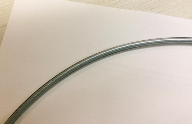
In order to conduct precision was higher pin to bend the arc. This is done by the printer to print two concentric circles right diameter so that their edges have been envelope studs. And slowly Gnehm it and constantly apply ourselves to the template, check. It is better to bend the entire rod (its length is 1 meter) - so it's easier. Short - do not bend gently hands. 10 minutes everything was ready.
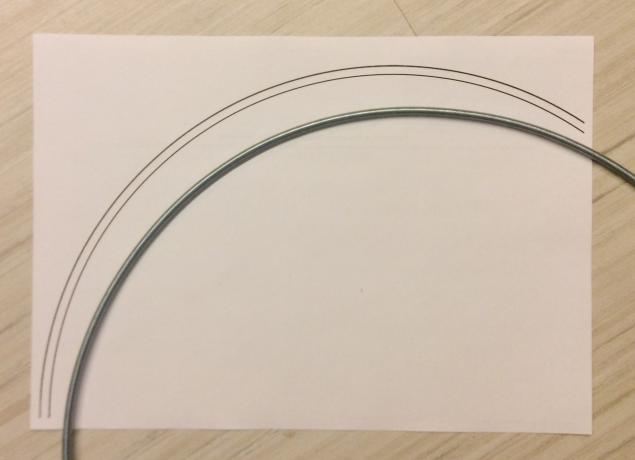
Dremel cut off the excess. I left a segment of about 25 centimeters. That's enough for more than 5 hours of doing.
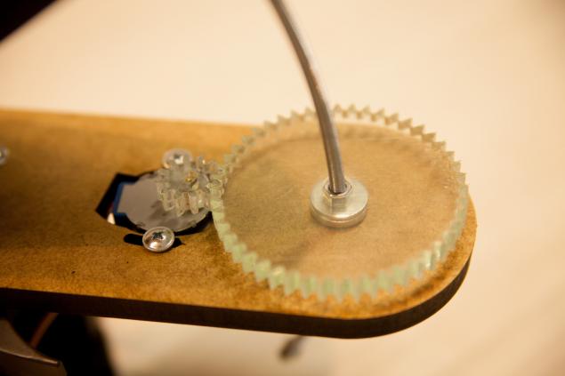
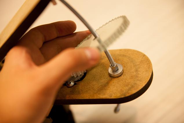
Putting it all together:
Check the rotation on a pre-written sketch for Arduino.

Googling, I discovered that they can be easily bought. But that's the price bites. For example, the cheapest Vixin Ploarie Star Tracker costs $ 400 + of Delivery. Yes and lifting his doubt. In the future, I planned to go from wide-angle lens and a 70-200 / 2.8 that came with the camera weighs under half kg.
In the search turned out that people do to themselves so called Barn Door Trackers: times , два and другие. Simply put - the door of the shed. The operating principle is simple - two boards connected by a canopy door. One of them is rotated at the same speed as the earth around its axis. The axis of the canopy always aim at Polaris. The bottom board is placed on a tripod and placed on the movable half tripod head with the camera.
Under the cut a lot of pictures.
I set about trying to make this tracker. Because without it you can only shoot stellar tracks of this type.

According to estimations for this almost everything was on hand. Decided to take as a basis this tracker . There you have a description of the methodology of calculation of the basic parameters.
The material has been selected for dostochek 10mm MDF as it was the experience of laser cutting in the studio. The material is cheap, easy to use. In terms of reliability far too early to say. Look at the trial operation.
First, in the CAD-program I drew a model of what should have been done. To do this it was necessary to calculate the radius and rotational speed of the stud. By my estimation radius turned 182.85mm for M5 studs with 0.8mm thread pitch and speed nut 1 / min. Hairpin M5 was chosen as a compromise between strength and thread pitch.


Because subsequently wanted to shoot at 70-200 / 2.8 then had to count how many steps the motor to do in a minute that there were no blurring within a single pixel. After all I did prikidok tenfold margin for error that would not manufacture design dramatically worsened the situation.

To rotate the nut on the stud in the original design of the gear used. But to find gear for adequate money and did not work. Tolna were on e-bay and then to $ 10 + delivery month. Therefore, the gears also decided to cut laser of MDF or acrylic.


As stepper motor used Chinese 28BYJ-48. Their long I lay several pieces, all wanted to play. They stand with the card controller is less than $ 2 on ebay delivery. It is powered from 5-12 volts. Makes one revolution of the shaft of the 64 steps. It also has a gearbox with koefitsientom close to 63.68395: 1. Thus, the external axis is rotated in steps 2037 4-step mode or 4075-steps in the 8-step mode. Torque he is not great, but for this problem it is more than enough. On the Internet, write that turned out to get him on the order of 15 / min, but with an increase in power up to 12V. I decided that was enough for me 4 rev / min and made the gear ratio 4: 1 that would be for four turns of the engine nut on the stud makes one revolution.


In the store I bought a shed door with minimal backlash. Its size and width became dostochek. There's also bought a hairpin. In another shop scored fixings. On fasteners, cutting MDF, loop took about 100 USD. ($ 8.3). On ebay ordered a small ball head but so far has put the old conventional tripod.
In the bottom half I made holes for attachment to a removable platform photo head Manfrotto 804RC2 whiling away I was. Also made the holes for the engine. I have provided a distance adjustment between gears by rotation around one of the motor mounting holes.
When I was pleased with the drawings, I took him to cut and brought here are wonderful but strong-smelling fumes details.

Gears and cut out of acrylic and MDF. With acrylic turned bad ends of the teeth poplavilis. I had to treat them with a file. Subjectively, in the course of MDF turned softer. But look on the battlefield.

Fixing the gear to the nut is very simple - a hole in the form of hexagon-tolerance. Acrylic - 8mm. Just put the 2 nuts M5.

In order to conduct precision was higher pin to bend the arc. This is done by the printer to print two concentric circles right diameter so that their edges have been envelope studs. And slowly Gnehm it and constantly apply ourselves to the template, check. It is better to bend the entire rod (its length is 1 meter) - so it's easier. Short - do not bend gently hands. 10 minutes everything was ready.


Dremel cut off the excess. I left a segment of about 25 centimeters. That's enough for more than 5 hours of doing.
Putting it all together:

Check the rotation on a pre-written sketch for Arduino.
& lt; code class = & quot; cpp & quot; & gt; #include & lt; AccelStepper.h & gt; #include & lt; LiquidCrystal.h & gt; 8 #define HALFSTEP LiquidCrystal lcd (8, 13, 9, 4, 5, 6, 7); int adc_key_val [5] = {50, 200, 400, 600, 800}; // Motor pin definitions #define motorPin1 3 // IN1 on the ULN2003 driver 1 #define motorPin2 4 // IN2 on the ULN2003 driver 1 #define motorPin3 5 // IN3 on the ULN2003 driver 1 #define motorPin4 6 // IN4 on the ULN2003 driver 1 int NUM_KEYS = 5; int adc_key_in; int key = -1; int isRun; double speeds = 271.6; int maxspeed = 1245; AccelStepper stepper1 (HALFSTEP, motorPin1, motorPin3, motorPin2, motorPin4); void setup () {lcd.clear (); lcd.begin (16, 2); lcd.setCursor (0, 0); lcd.print (& quot; Stopped & quot;); lcd.setCursor (0, 1); lcd.print (& quot; Speed & quot;); lcd.print (speeds); lcd.print (& quot; & quot;); isRun = 0; stepper1.setMaxSpeed (maxspeed); stepper1.setSpeed (speeds); } Void loop () {adc_key_in = analogRead (0); // Read the value from the sensor key = get_key (adc_key_in); // Convert into key press if (key & gt; = 0) // if keypress is detected {if (key == 1) {speeds + = 0.1; delay (50); } If (key == 2 & amp; & amp; speeds & gt; 0) {speeds - = 0.1; delay (50); } If (key == 0) {speeds + = 10; } If (key == 3) {speeds - = 10; } If (speeds & gt; maxspeed) {speeds = maxspeed; } If (speeds & lt; -maxspeed) {speeds = -maxspeed; } If (key == 4) {isRun = 1 - isRun; lcd.setCursor (0, 0); if (isRun == 1) {lcd.print (& quot; +++ Running +++ & quot;); } Else {lcd.print (& quot; Stopped & quot;); } Delay (250); } Lcd.setCursor (0, 1); lcd.print (& quot; Speed & quot;); lcd.print (speeds); lcd.print (& quot; & quot;); stepper1.setSpeed (speeds); delay (50); } If (isRun == 1) {stepper1.runSpeed (); }} Int get_key (unsigned int input) {int k; for (k = 0; k & lt; NUM_KEYS; k ++) {if (input & lt; adc_key_val [k]) return k; } If (k & gt; = NUM_KEYS) k = -1; // No valid key pressed return k; } & Lt; / code & gt; pre>
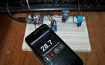
I used the LCD Keypad Shield that would be convenient to pick up the speed of rotation.
There kpopka Start / Stop. There increment / decrement by 25 steps and 0.1 step. The speed is measured in meters per second. The design speed should be 271.6 steps per second. But check out yet because I can not constantly rains.
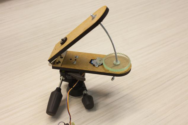
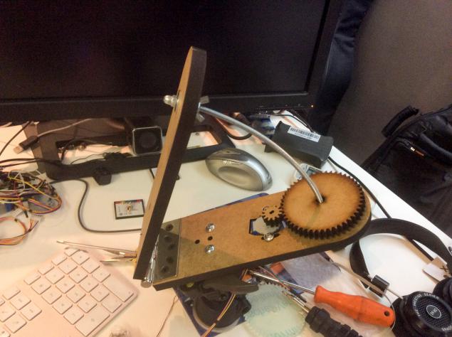
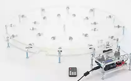
General view of the resulting structure
There are two Arduino. Do not pay attention. One is used as a power source for the motor.
Video process works
Now the weather is nasty. Showers. Once the star will be seen proceed to mount testing in the field.
Source: habrahabr.ru/post/227499/


The most popular idea of robots on Kickstarter
Oculus buys a group of the best industrial designers