Weather Station: from idea to realization
Read a lot of articles on the development of your device, and wanted to talk about their experiences. It happened a few years ago, on the 4 th year of uni. Now I would have done much differently, but at the time I was just starting to learn electronics, it is - my first device, so do not judge strictly.
I always wanted something more than an ordinary thermometer outside the window or the LCD screen weather station with temperature in the street and in the room. So when I started thinking, "what is done" in order to start discovering the world of microcontrollers, the answer was found by itself - a weather station. Naturally, displaying degrees outside and inside the room, humidity and pressure. And with the light - I always liked the implementation of weather forecast on Yandex - one look at the background enough to understand, it will be warm or cold, and how.
All further functionality has been defined a little brainstorming. The presence of the backlight is definitely a plus, but what about at night and in the evening? I decided to install the IR sensor that reacts to the approach. At the approach to the instrument at a comfortable distance illuminates, at other times the default screen is off. Using IR pushed to implement the control unit also on the IR channel - via console (initially had concerns about interference, but they have not been confirmed). It is natural for such a device availability hours.
As a basis for the system was chosen Arduino, I was just starting to learn. Arduino itself I consider now (and then) as a framework - primarily software that allows you to quickly build the necessary system connecting if necessary plugins library. Yes, we can write in pure C / C ++, but most ordinary tasks it gives only a slight increase in performance, almost invisible against the background of simplicity and ease of loading sketches in Arduino, as well as an extensive collection of libraries for working with various glands. (Of course, there are special challenges, but now it's not about them).
In the hardware implementation of the same, I prefer to use the blue Arduino board only at the stage of prototyping to "maketke", and at the end of the development of devices are usually designed one single board with a microcontroller and everything else. So it was at that time.
Selection of components I started with the screen. Quickly found a wonderful display with RGB-backlit www.adafruit.com/products/398 , which allowed to obtain almost any color. It is built on the popular HD44780 chip and supports a huge number of libraries, including LiquidCrystal in Arduino.
I also inquired about the price of individual production displays. Minimum price for 1 copy of the monochrome LCD (as in a typical meteorological station) at prices that time was of the order of EUR 1 000, for non-commercial project in one copy I found a price tag impractical.
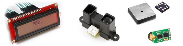
As an infrared sensor was chosen Sharp GP2Y0A02YK0F . Important characteristic in my case is the detection range of facilities, this sensor is equal to 1.5 m, while many other sensors does not exceed 30 cm. As shown itself exploitation, for the small screen 16x2 half meters - really the optimal distance.
As the pressure sensor was selected Bosch BMP085 , working on I2C , humidity HH10D - with frequency output. I'll tell you that right now I would in any case have not used the latter, and would prefer I2C-only options, such HTU21D.
As the external temperature sensors are used all your favorite DS18B20 . Their great advantage is the ability to connect (and disconnect if necessary) 1 bus multiple sensors without the need to change the code. With wireless transmission of temperature data I in my first project, I did not communicate, the more that I had the opportunity to lay the wires without compromising aesthetics.
IR receiver was taken most typical such TSOP382. Remote control for remote weather station was from some of the DVR. Buzzer (it squeaker) - most common piezo buzzer.
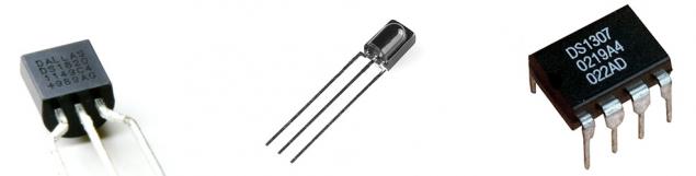
As a real-time clock, I chose DS1307 , also working on I2C, moreover, I had a tiny chip flash memory 24AA256 64 KB with I2C-interface. I added it to the project out of pure curiosity - try to work with external memory, writing data into it about the weather conditions. Power for the project - the external, from the power supply. At the entrance stands converter / voltage LM7805 , supply node itself is very similar to that used in the Arduino (although not is a clone).
I iterate development, so much easier to debug and meet new field. At the first stage, with the thermometer DS18B20 read the data and displayed on the LCD screen. The next - temperature values were converted to RGB-code for illumination.
Here I lay in wait for the color feature. Color Management screen is performed using pulse-width modulation for each of the three LED lights (using the standard library) with 256 steps - seemingly quite normal 24-bit color. Unfortunately, the wavelengths for the colors R, G and B of the monitor and the LED lights are very different, and because of this, the usual color, like # ffff00, against the background of my LCD screen look completely different ("leave aside"). So I had to write a C # program with three sliders and color picker'om broadcasting the three color components in a serial Arduino. Then had to remember the basics of mathematics and create a function that converts the temperature in degrees Celsius in the RGB-color scale. Naturally, I am no longer limited to the yellow-blue scale Yandex, and used other colors - on the basis of their associations.
The next step was to connect IR rangefinder, temperature and humidity sensors. And if the first two did not have any difficulties (except soldering BMP085 in LCC8-case), then the humidity sensor will bring a lot of problems.
The thing is that the total value of the relative humidity is calculated using the formula, one of the arguments which is the frequency of the output square wave sensor. Frequency measurement is performed using the hardware timer microcontroller. In 328, unfortunately, these timers are only three, and most of them are already involved at Chimay to illuminate the display. (Now I do not remember all the details, maybe missed something).
From this situation there were several exits. If I developed a device today, I would definitely have used only I2C-sensors. Another option was to use a more powerful microcontroller. I then chose a third option - to install a separate microcontroller to work with sound (tweeter) and a backlit display (remember, this was primarily an educational project, and I was curious to try to organize cooperation between the two MC). It also passed the conversion function of temperature in color, making it easier for a few kilobytes of main firmware MK (Atmega328 in the memory size of the program is only 32Kb, my firmware eventually come close to this limit). The interaction between the MC was still organized on the I2C.
Thereafter were added control, clock, flash memory. The next step was to write a user-friendly menu, the addition of software features (such as blocking the backlight in the current state, the regime of large numbers - as in street clock, scrolling all the parameters), support for multiple temperature sensors with their addition / removal online (yes, I know that it is better not to do). It is quite a usual thing for the PC - and unusual at first you collected for the device when no schema changes several times increases the functionality of the project ...
Remote use some its proprietary protocol. I did not engage in reverse engineering it, I was quite enough hexadecimal representation of each button, I received from the library IRRemote. For the flash memory I choose to record weather data every 10 minutes, at a length of 16 bytes in the record of this is enough for 4 months.
The code responsible for working with flash memory LOGGER.h
& lt; code class = & quot; cpp & quot; & gt; #ifndef LOGGER_h #define LOGGER_h #include & lt; WProgram.h & gt; class LOGGER {public: LOGGER (int); void storeRecord16 (byte * buffer); void getRecord16 (unsigned int address, byte * buffer); int getAddress (); void setAddress (int); private: int _FlashI2CAddress; void _getAddress (); void _setAddress (); unsigned int _addr; }; #endif & lt; / code & gt; pre> LOGGER.cpp
& lt; code class = & quot; cpp & quot; & gt; #include & lt; WProgram.h & gt; #include & lt; Wire.h & gt; #include & quot; LOGGER.h & quot; / * MEMORY MAP: 0000 - MSB of last written address 0001 - LSB of last written address ... 0040 - 7FFF - storage, * / LOGGER :: LOGGER (int a) {_FlashI2CAddress = a; } Void LOGGER :: storeRecord16 (byte * buffer) {byte c; // Get address LOGGER :: _ getAddress (); // Increase addr delay (5); _addr + = 16; if (_addr & gt; 0x7FF0) _addr = 64; // Store buffer Wire.beginTransmission (_FlashI2CAddress); Wire.send ((byte) (_addr & gt; & gt; 8) & amp; 0xFF); // MSB Wire.send ((byte) (_addr & amp; 0xFF)); // LSB for (c = 0; c & lt; 16; c ++) Wire.send (buffer [c]); Wire.endTransmission (); delay (20); // Save new addr LOGGER :: _ setAddress (); } Void LOGGER :: getRecord16 (unsigned int address, byte * buffer) {byte c; // Set address Wire.beginTransmission (_FlashI2CAddress); Wire.send ((byte) (address & gt; & gt; 8) & amp; 0xFF); // MSB Wire.send ((byte) (address & amp; 0xFF)); // LSB Wire.endTransmission (); Wire.requestFrom (_FlashI2CAddress, 16); for (c = 0; c & lt; 16; c ++) if (Wire.available ()) buffer [c] = Wire.receive (); } Void LOGGER :: _ getAddress () {byte c; Wire.beginTransmission (_FlashI2CAddress); Wire.send (0); Wire.send (0); Wire.endTransmission (); Wire.requestFrom (_FlashI2CAddress, 2); for (c = 0; c & lt; 2; c ++) if (Wire.available ()) _addr = _addr * 256 + Wire.receive (); } Void LOGGER :: _ setAddress () {Wire.beginTransmission (_FlashI2CAddress); Wire.send (0); // Pointer Wire.send (0); // Pointer Wire.send ((byte) (_addr & gt; & gt; 8) & amp; 0xFF); // MSB Wire.send ((byte) (_addr & amp; 0xFF)); // LSB Wire.endTransmission (); } Void LOGGER :: setAddress (int addr) {_addr = addr; LOGGER :: _ setAddress (); } Int LOGGER :: getAddress () {LOGGER :: _ getAddress (); return _addr; } & Lt; / code & gt; pre>
Upload data produced by a team from the menu weather station (a bit like the old menu Nokia or Samsung, but without graphics) to the serial port.
After that, functionally complete weather station had been in the form of Arduino development boards and somewhere for a week. During this time, the tests detect possible hangup (due to seal failure outdoor temperature sensor). I redid the design of the sensor (today I would take only a factory, for example, such ), but also the possibility of deadlocks want to exclude in principle . In addition, I assumed that after 49 days of continuous operation an overflow function millis () , which, due to the specific algorithm, the firmware will also hang. The thing must be reliable! Therefore, the final touch was the activation of the system watchdog timer eventually hang any guaranteed not to last more than 2 seconds + 5 seconds to reboot (yes, in this digital age, even the weather station takes time to load.
So, the station is ready and working successfully. I believe that staying at this stage wrong. The device should be comfortable and have a finished appearance, so that they can enjoy the comfort and show everyone, not just fellow geeks.
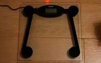
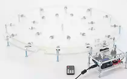
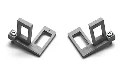
I started with a trip to the nearest radio store and housing choice. 20-30 various embodiments I he liked that Figure at the beginning of the article - for the minimum desired alteration, because of the possibility convenient to fix the outside casing rangefinder, so that it is not much protruded from the good ventilation (and thus more accurate readings of temperature in the room). Today, I think I would have ordered the printing on 3D-printer and did something here in this style:
(It's hard to find a similar picture, but I do not -modelirovanii 3D pros. The screen is located on the top of everything else in the stand). And, of course, no wires - 433MHz for sensors and Wi-Fi to connect to a PC.
After deliberation and fittings as better positioned all came the turn of the development board. In its first project, I used a system of Eagle. Draw the outline of the board, posted on her elements and connections (yes, this project I was doing the "wrong" way - without concept. More precisely, without the scheme in Eagle), the tracer with ease all divorced. Attributed to the production ...
Habré very fond of the theme of manufacturing printed circuit boards, so here I will do a retreat. Loot I am familiar, but I have no desire / ability to make boards, including contact with chemistry (ferric chloride that still a thing). But if the university has a small pilot production, where at very reasonable prices (~ $ 3 per sq.dm. at the time) can produce almost any bilateral PP. Technology - photoresist openings - from 0.6mm, the minimum width of the track - like 0.2mm (definitely not bigger, now I do not remember). Unfortunately, no solder mask, the metallization of vias for the price should not wait, but it's all solved. In the end, for prototyping (and dress ready for a day or two) and small-scale production can be done without masks (IMHO; Solder and manually mean big). Blockquote>
However, when I made the order, then about metallization of vias I have not thought of. Eagle safely use stem cells as such, and cost only 2-3-standing connections between layers. Man on extradition noticed it and kindly offered the thinnest wire to create transitions in the holes for the elements (ie, first through the hole to the top and bottom pad soldered posting, after which it has inserted itself stem cell). I tried to act like this, but the results and the amount of extra work is not encouraging. Had peretrassirovat dress created by the exclusion zone for the location close to all via PTH-elements. Here automatic tracer bring work to the end refused, and I had to raise the rest of the chain by hand (the desire and time to change the system design was not there). Sami vias eventually do exactly the same technology, but their number, I minimized. Soldering again ordered the dress was much easier.
Next - work with a drill, a knife and a file, the housing purchased for window screen mount for a fee. Pair evenings - and the apparatus body works successfully. And yet, something is missing ...
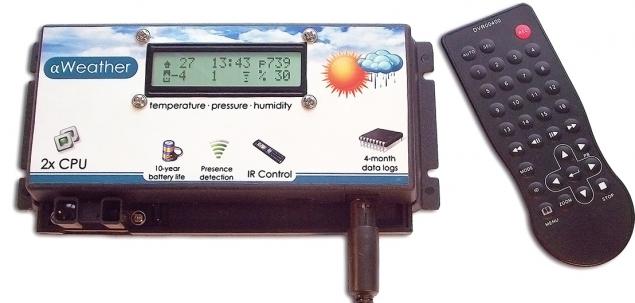
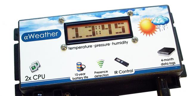
And not enough stickers on the front panel (especially after cutting through a window in it). Self-adhesive paper - a great thing for such tasks. What happened - a photo on the cover, do not judge strictly :) After this appearance of the device has changed radically ...
That's how (briefly) looked at me the way to develop my first device. Behind the scene left a lot of code, many different small decisions arising in the course objectives. The main thing I bought for myself - it's development experience, full of "bumps", understanding the principles of operation, plus a bonus was the weather station itself. Unique and one of a kind.
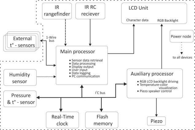
P.S. I know that many of the decisions are not optimal, but it is thanks to them (including), I now realize that the best and what not :). Attaching a functional diagram of a bonus in English and a few photos, and render the board.
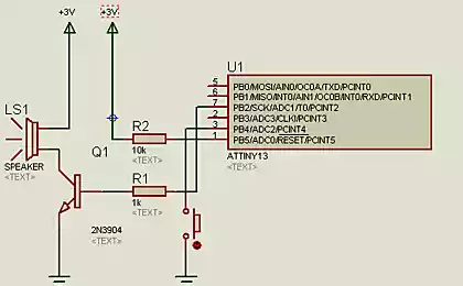
Functional diagram:
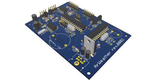
Render, real board without solder mask. Not shown in the lithium battery holder, piezo buzzer, DIN-connector (power, communication with the PC, sensors) and different small things. Moreover, in a real device microcontrollers are in sockets.
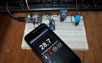
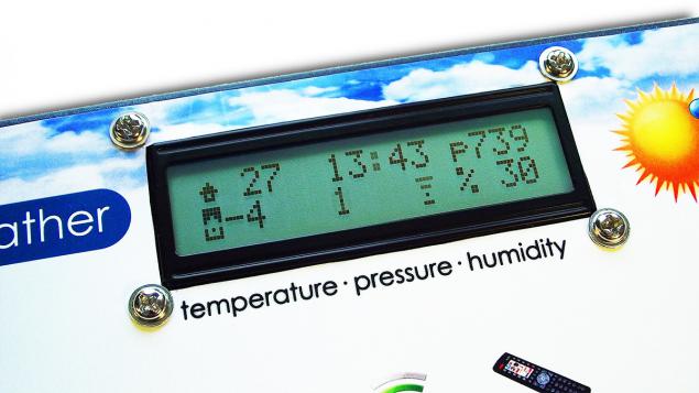
Mode "big numbers", for readability from a distance:
Source: habrahabr.ru/post/223829/