2149
Wi-Fi-based lamp module WizFi250
While the world's best minds are arguing about how to develop Интернета Things and promise enormous profits involved in this process is a high-tech companies, we decided to also do not sit idly by. Under the cut - the story of prototyping device control lamp on the basis of Wi-Fi-module WizFi250.
First, a bit about the Wi-Fi-module WizFi250. Appearance - pictured:
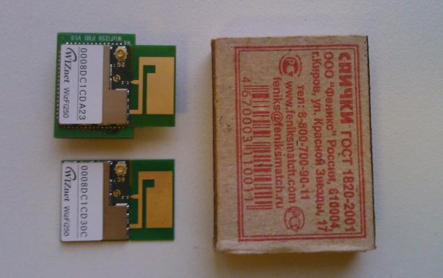
The module supports the standards IEEE 802.11b / g / n and managed by AT-commands via UART (or SPI) or through the WEB-interface. Full description of AT-commands WizFi250 can be found здесь.
Module has a PCB-antenna, but provides connectivity and an external antenna. Switching between the antennas - automatic or command AT + WANT. PCB-antenna can be cut (perforation available) - then the dimensions of the module will be reduced to 17 x 20 mm.
Wired interfaces: UART, SPI, GPIO.
Manufacturer - WizNet, Korea, here module datasheet WizFi250 .
To test there Dresses Arduino UNO Wi-Fi Schild:
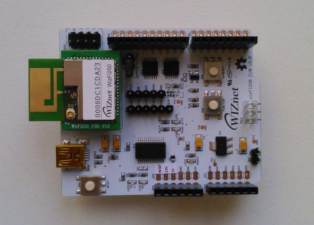
But it is "in style", as for joint use with the Arduino they need to finish a little. Here's a fee and we will use for prototyping in conjunction with the board Arduino UNO.
In general, such a plan: to connect via Wi-Fi to use the module WizFi250, management module and lamp - Arduino UNO, control commands transmitted from the phone or tablet via Wi-Fi in the form of UDP packets or TCP.
Oh, and the module provides two useful indicator output:
1) WiFi_STATUS: low level - Wi-Fi running, high - Wi-Fi turned off.
2) MODE_STATUS: High - command mode (Command Mode), a low level - mode data (Data Mode).
On board debug these signals displayed on the LEDs "Wi-Fi" and "Mode", respectively, which is useful for debugging.
Supply voltage WizFi250 and inputs and outputs - 3 of 3 V. Arduino UNO - pyativoltovy, t. E. To manage Wi-Fi module need to negotiate. On board debug WizFi250 found two chips Quad converters levels TXS0104EPWR, one of which, IC4, is used to interface SPI, other, IC5 - RESET signals and GPIO14 Wi-Fi module. But conversion levels UART interface for debugging board WizFi250 somehow not provided ... That's what I had in mind when he wrote about small improvements.
The idea is to convert the level lines Rx and Tx UART can try to use the remaining two channel converter IC5, but soldered to the thin legs level converter chip debug and modify not want to, so we used the old-fashioned way to convert signal levels with a pair of transistors:
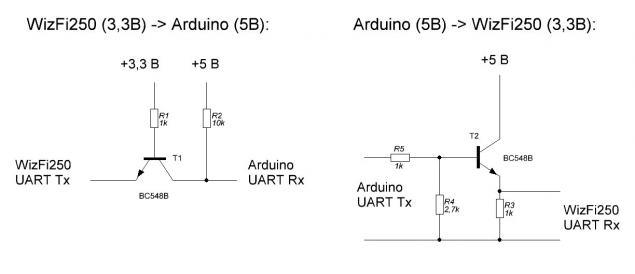
The scheme is simple, it may be the only trick - to use 1k resistor (R3) of the inverter output 5V - & gt; 3, 3B. When using a resistor with higher ratings scheme is not working properly, vsyazano is the fact that at one point there are two choices: FTDI FT232 chips and our homemade. Not good, but the layout is quite acceptable.
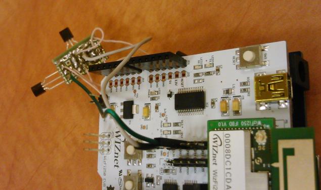
As a result of our development board WizFi250 with homemade Voltage Level Translator as follows:
The module can operate in two modes: Access Point (AP, Access Point, when connected to it other Wi-Fi-devices) or client (STA, Station, when he connects to the access point).
You can set different security settings (encryption), enable / disable the internal WEB-server.
The module supports modes UDP Server / Client, TCP Server / Client, TCP Secured Server / Client (using SSL).
Can be installed or data mode (Data Mode, Transparent mode on UART module are given clean data that come over TCP or UDP, the module does not accept control commands) or command mode (Command Mode, the data is sent and given to the UART in "wrappers" module continues to accept commands). The transition from data mode to command mode - using traditional +++.
Before you start module must be entered in the desired mode. This initialization can be carried out, or every time you turn on, or use the auto-configuration module at startup.
Here are a couple examples of module initialization:
1. If we need an access point mode, UDP server and data mode, a sequence of commands will initialize this:
- AT + WSET = 1, WizFi250 - sets the mode of the access point with the name WizFi250
- AT + WSEC = 1, WPA2, 12345678 - ask the security mode and password
- AT + WNET = 0, 192.168.10.1, 255.255.255.0, 0.0.0.0 - prescribes the IP-address and subnet mask (if the access point first and last parameters are ignored)
- AT + WJOIN - run Wi- Fi
- AT + SCON = O, USN,,, 7777, 1 - UDP server, port 7777, data mode.
2. If you want a client mode, TCP server and command mode:
- AT + WSCAN = WizFi250 - scanning the access point name WizFi250
- AT + WSET = 0, WizFi250 - sets the mode of the station, the name of the access point
- AT + WSEC = 0, WPA2, 12345678 - prescribes security mode password
- AT + WNET = 0, 192.168.10.2, 255.255.255.0, 192.168.10.1 - DHCP is disabled, IP-address, subnet mask, gateway
- AT + WJOIN - connect to an access point
- AT + SCON = O, TSN,,, 7777, 0 - start the server's TCP port 7777, command mode ul > After initializing the Wi-Fi-module we can only analyze data from the module UART, and enable or disable our light bulb in the event of the appropriate commands.
Arduinovsky sketch hardly makes sense given here: it is the most simple and do not think that someone will be useful / interesting.
The switching circuit consists of a light bulb pyativoltovogo relay, transistor switch and a pair of discrete components:
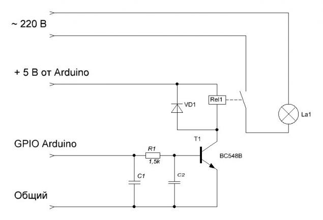
As a control output Arduino used GPIO 13 (initialization string: pinMode (13, OUTPUT);)
In general, the layout turned out such:
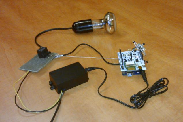
In the black box - power supply 220V ~ - & gt; = 9V.
For a quick test with control lamp tablet or smartphone on Android, you can use ready-made programs that can send packets to TCP / UDP, such as UDP Sender or TCP / UDP Server. Similarly - for iOS.
In general, testing has shown that even when using the simplest algorithms can achieve stable operation of the system.
Other options - use the built-in capabilities WEB-server module management GPIO (5 pcs.) And the ability to customize the firmware module manufacturer. Both options are interesting in that they allow to do without an external controller / processor. But that's another story.
PS Video will try to add a little bit later.
Source: geektimes.ru/post/242002/


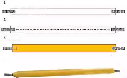


Parse RC paper airplane PowerUP 3.0 for parts
Scientists suggest the use of television frequencies to create a super Wi-Fi network