611
Smart socket Redmond SkyPlug RSP-100S
In this article I want to share with all the important information about the analysis and the circuitry of a device such as a smart socket, Smart plug SkyPlug REDMOND RSP-100S, which, through wireless communication via the Bluetooth interface can be connected with the special app installed in their smartphones based on operating systems Android and iOS and allows you to remotely control the inclusion of electric lighting appliances in the network ~ 220 V (or 230 V).
Somehow in one of the branded stores on sale, I bought two of these sockets to use for other purposes: to control the aquarium lighting and power management Wi-Fi router to which is connected a 4G USB modem. Sometimes, the operators will snap so that the disconnection and reconnection does not help, helps only a full power off of the USB modem, or, alternatively, the power of the WiFi router as a whole. Since this is a frequent problem and my router with a USB modem is installed on the second floor (there is a more confident reception), and Internet I use on the first floor, then run to the second floor and briefly disconnect the WiFi-router annoying, because man is a lazy animal. Therefore, the idea to control the "reset the Internet" remotely via Bluetooth using a socket.
According to the characteristics indicated on the packaging and in the instruction manual, the load can be connected to any household (in principle and not only the household) appliance with a capacity not exceeding 2.3 kW. But, of course, to be sure – it will stand the power this socket, it is necessary to analyze the design of the circuitry and used the socket components and to identify the shortcomings of the device on which I want to draw attention in this article. And to make it more clear, it would be nice to see a diagram of this socket. The scheme I tried to find online, but for a long time digging, did not find this information anywhere and as a result had to copy it yourself.
But why did I need the schema of this outlet if I had them adapted to such simple needs? This is what I will discuss in the next article, let it be a small intrigue.
Well, I wonder? Under the cut details.
1 DESIGN SMART SOCKETS
The first thing that attracts in this socket, is a compact design, it is not bulky, the body without flaws, all smooth and aesthetically pleasing.
Twelve million four hundred ninety seven thousand nine hundred forty eight
Seventy million nine hundred ninety four thousand nine hundred seventy six
Figure 1 – External view of the smart sockets
But as they say, looks can be deceiving, and you always want to look inside and see there, whether it's beautiful outside.
So, Unscrew those screws with the slots under the "star", since the bit on the screwdriver for these screws I have in my Toolbox found. Open and look at:
Eighty million six hundred forty five thousand seven hundred ninety seven
Forty one million four hundred ninety six thousand seven hundred fifty eight
Figure 2 – the Internal contents of smart sockets
On the pictures you can see the circuit Board with the electronic circuit. Circuit Board made to the size of the outlet is quite compact, but not without flaws. The first flaw that is evident is that the fee after installation and Assembly was not washed from the flux, for in some places was straight so violent flux, which the Chinese (Yes, Chinese, this socket was made in China) not laundered. In the pictures of the flux is not visible, because, I confess, I to shooting washed, to better see all the details of the Board. Also immediately revealed another drawback is the Board is not covered with varnish or other special coatings that protect the conductors, components, and places the rations of the components on the Board from moisture, salts, fats and other substances that pairs of them can be in the kitchen, the bathroom and other rooms. And if, say, someone wants to use this outlet in the garage, there could still be more aggressive environment. But, I'm not sure that this socket can be used outside the premises, and it is not known whether it can withstand negative temperatures of the environment.
The images show that from the base (the lower part of the socket with pin contacts) Jack (the upper part of the outlet socket under the plug load) reaches a conductor of relatively large cross section is the wire from the grounding, he's all-in-one and connected by soldering to remove the socket, I had this wire to unsolder.
Fifteen million twenty two thousand five hundred fifteen
Figure 3 – Installation grounding link load
In the picture of the nest you can see the method of attachment of the brace contacts the ground. I have the feeling that the Chinese, wearing the brace in place, making it a melting protrusions of a conventional soldering iron. Is it really impossible to make some kind of special device for melting these projections? Of course, work is not affected, but still, there is a possibility that the bracket will come off when failed to connect to the outlet of the appliance and as a result it will refer to charges where there is phase voltage and can cause short circuit that will damage the socket, but maybe the wiring in the room.
And here is the Board installed in the base socket
Thirty million one hundred ninety four thousand eight hundred forty eight
Figure 4 – Setting fees on the basis of smart sockets
I tried to separate the charge from the base, but it failed on the first attempt. Then, looking in the gap between Board and base, it became clear that holding a charge. It is directly soldered to contacts extending from the pins to the circuit Board and soldered, they are in the locations marked on the Board as X3 and X4. Take the soldering iron and desoldering pump and removed those contacts from the solder, gently, effortlessly, lifting the charge to separate it and not to rip out the hole plating on these contacts. So, charge is separated, and the inside looks as shown in the photo below.
Sixty one million one hundred twenty seven thousand eight hundred sixty eight
Figure 5 – Mounting of the contact plug smart socket
On the basis of immediately apparent that the brass contacts extending from the pins to the Board, to the pins join raskladyvanii, in my opinion, is not a very reliable connection. And one more note: the socket housing is made of a fusible polymer, whereby, if under load high power contact pins of a smart socket with the contacts in the wall outlet is not good enough, in this place the possible strong heating and a smart socket, it can in place of the pins will melt, which will lead to its deterioration. It is also seen that the brace contacts the ground in the center has a hole and under the hole you can see the counter (as part of the design of the plastic base) under the screw or screw. Again, the Chinese faked – saved screws. In this economy, I determined that the bracket can be bent if the outside of the sides on it will press the spring contacts grounding wall outlet (or network extenders). The ends of the outer contacts of the clamp should fall into the grooves from which the contacts under the influence of the return spring contacts can fall out due to the fact that the clip is not fastened by screw to the base and, accordingly, does not have sufficient stiffness clamp.
We go further and consider the circuit Board sockets.
Ninety five million two hundred forty eight thousand seven hundred thirty eight
Figure 6 – Printed circuit Board – top view
With the upper hand on the Board immediately catches the eye is another small fee. Once it becomes clear that this Bluetooth module is formed on a separate scarf and this scarf shows the installed chip with marking N51822 and the antenna in the form of zigzag printed conductor. Looking for Datasheet for this chip. My favorite site to search for the datasheets on imported parts alldatasheet.com gave no results, just a thought, it's likely that the chip is not from a particularly well-known manufacturer that is not included in the lists of this famous site. Then looking for Datasheet via the search engines, as a result, it was found and the microchip was from the company "Nordic Semiconductor", which I've never heard before, it may have encountered its products, but did not attach any importance. The full name of this chip here is: nRF51822, according to Datasheet, this Multiprotocol Bluetooth controller 2.4 GHz with low power consumption.
The Board also shows a single button that allows you to control on/off loading by hand, next to the SMD LEDs, one green led indicates it and the other one red – used to display the authorization mode on Bluetooth with a smartphone.
In addition there is a varistor to protect against overvoltage in the network and a disk element green colour, which, as it turned out, is a thermistor, judging by the marking on the Board – TC1. You can still see the diode bridge, it is marked with pole conclusions.
Also from the top side of the Board you can see two fairly large holes, designated as X1 and X2 in them is a plug load and on the other side of the Board plug load is connected to the contacts of the socket soldered to the Board.
On the PCB there is a seat XP1, where nothing is installed, most likely this can be soldered connector cable programmer for in-circuit programming of the Bluetooth controller because the pads XP1 associated with Board Bluetooth module.
About the rest of the elements installed on the top side of the Board will be looking at the circuit diagram below.
Turn the Board and see that on the lower side of the installed solenoid type Y32F-SS-112HM from, also not known to me previously of the firm, "Yuanze Electric". Digging in the Internet, specific dataset this relay is not found, but found the same in design and by name, and found that the coil of this relay is designed for voltage of 12 V, which means that the device needs to eat approximately the same voltage. Well, there is no doubt that such a small relay allow to commutate such powerful loads (10 A/230 V), I think that it is not how long it will last, or contacts will be warm and will melt the plastic elements of the design of the relay or the contacts will burn.
Eighty seven million seven hundred eighty eight thousand eight hundred eleven
Figure 7 – Printed circuit Board – bottom view
On both sides of the relay can be seen copper (or Mednoye, but steel) contacts for connection to the load. As I found out initially, as I started to use this socket, these contacts are spring loaded insufficiently, i.e. they do not quite return to their original state after use loads that have a plug "Euro" pins which have a diameter of 5 mm, the socket contacts expand over time and the result will not be able to use electrical plug contacts which have a diameter of 4 mm, for example, a charger for smartphones. I for a more reliable connection at its outlet slightly pursed these contacts for some time enough.
Also, we should notice two rather large SMD capacitors labeled C3 and C5. It is obvious that these capacitors built bestransportnye sources of supply for all the circuit elements of the socket.
Even here, you can see other circuit elements, the functions and the use of this socket will become clear after the analysis and designing of the schematic diagram of the outlet.
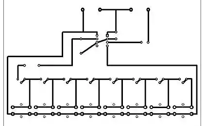
2 IS A SCHEMATIC CIRCUIT DIAGRAM OF SMART SOCKET
After a detailed analysis of printed circuit boards, all conductor traces and elements installed on the Board I drew the concept of the smart sockets.
Below is a schematic diagram of the smart socket with the exception of shawls Bluetooth module, because there is most likely a switching circuit IC nRF51822 is typical and can be seen in some datasheets on the IC.
It should be noted that the controller firmware of the nRF51822 smart sockets I didn't remove, because I do not have the technical means to do so, and while I'm not interested in the firmware, copy these outlets I'm not going, so if anyone needs it – try it yourself but then unsubscribe about results, if that.
Diagram of smart outlets is not so difficult as it seemed at the beginning and consists of:
— varistor that protects from spikes in voltage as the socket and the load;
— fuse;
— transformerless power supply based on high-voltage ceramic capacitors, damping resistor, small diode bridge rectifier, two Zener diodes, 1.3 W 12 V linear regulator for the 3.3 V power supply for Bluetooth module;
— Board Bluetooth module, which consists of controller with Bluetooth radio interface on the basis of IMS nRF51822, which you can flash the firmware to perform any action both manually and remotely via Bluetooth interface;
another important component is the solenoid, which is controlled by the Bluetooth module via the transistor switch, relays, delivers or releases tension electrostatically network going to the load;
buttons manual load control;
diagram display modes on the basis of the LEDs through the transistor switches are controlled by the same Bluetooth module.
Sixty three million ninety two thousand one hundred ninety four
Figure 8 is a schematic circuit Diagram of smart socket
In conclusion, I want to tell you that scheme I drew as it is, with an accuracy of positional notation and the values of the applied elements. At first glance, throw that on the schematic reference designators are numbered randomly, but there you have it – the diagram I drew as I think it would be easier to read, and I don't know how it was painted from the developer, maybe he had it backwards, and numbering of such. Renumber the components I did not, because then there would be differences with the markings on the PCB. And, by the way, all the mistakes of the developer in the circuit I is also depicted as it is. More precisely the error I found one, if there are those who also see it in a personal email, do not immediately identify her. The first who sent the correct answer, the prize, let it be 50 rubles. on the mobile phone account, for example. Then this error will be discussed in the comments if you want.
PS Forgot to just write that pin numbers shawls Bluetooth module is numbered conventionally me, it's not the pin numbers of the IC kontrolera is the numbers of the solder pin of the Board, I counted counterclockwise, starting from the group of findings that consecutive 5 PCs are connected with the common wire circuit (GND).
P. S. And remember, only by changing their consumption — together we change the world! ©
Source: geektimes.ru/post/278262/
Somehow in one of the branded stores on sale, I bought two of these sockets to use for other purposes: to control the aquarium lighting and power management Wi-Fi router to which is connected a 4G USB modem. Sometimes, the operators will snap so that the disconnection and reconnection does not help, helps only a full power off of the USB modem, or, alternatively, the power of the WiFi router as a whole. Since this is a frequent problem and my router with a USB modem is installed on the second floor (there is a more confident reception), and Internet I use on the first floor, then run to the second floor and briefly disconnect the WiFi-router annoying, because man is a lazy animal. Therefore, the idea to control the "reset the Internet" remotely via Bluetooth using a socket.
According to the characteristics indicated on the packaging and in the instruction manual, the load can be connected to any household (in principle and not only the household) appliance with a capacity not exceeding 2.3 kW. But, of course, to be sure – it will stand the power this socket, it is necessary to analyze the design of the circuitry and used the socket components and to identify the shortcomings of the device on which I want to draw attention in this article. And to make it more clear, it would be nice to see a diagram of this socket. The scheme I tried to find online, but for a long time digging, did not find this information anywhere and as a result had to copy it yourself.
But why did I need the schema of this outlet if I had them adapted to such simple needs? This is what I will discuss in the next article, let it be a small intrigue.
Well, I wonder? Under the cut details.
1 DESIGN SMART SOCKETS
The first thing that attracts in this socket, is a compact design, it is not bulky, the body without flaws, all smooth and aesthetically pleasing.
Twelve million four hundred ninety seven thousand nine hundred forty eight
Seventy million nine hundred ninety four thousand nine hundred seventy six
Figure 1 – External view of the smart sockets
But as they say, looks can be deceiving, and you always want to look inside and see there, whether it's beautiful outside.
So, Unscrew those screws with the slots under the "star", since the bit on the screwdriver for these screws I have in my Toolbox found. Open and look at:
Eighty million six hundred forty five thousand seven hundred ninety seven
Forty one million four hundred ninety six thousand seven hundred fifty eight
Figure 2 – the Internal contents of smart sockets
On the pictures you can see the circuit Board with the electronic circuit. Circuit Board made to the size of the outlet is quite compact, but not without flaws. The first flaw that is evident is that the fee after installation and Assembly was not washed from the flux, for in some places was straight so violent flux, which the Chinese (Yes, Chinese, this socket was made in China) not laundered. In the pictures of the flux is not visible, because, I confess, I to shooting washed, to better see all the details of the Board. Also immediately revealed another drawback is the Board is not covered with varnish or other special coatings that protect the conductors, components, and places the rations of the components on the Board from moisture, salts, fats and other substances that pairs of them can be in the kitchen, the bathroom and other rooms. And if, say, someone wants to use this outlet in the garage, there could still be more aggressive environment. But, I'm not sure that this socket can be used outside the premises, and it is not known whether it can withstand negative temperatures of the environment.
The images show that from the base (the lower part of the socket with pin contacts) Jack (the upper part of the outlet socket under the plug load) reaches a conductor of relatively large cross section is the wire from the grounding, he's all-in-one and connected by soldering to remove the socket, I had this wire to unsolder.
Fifteen million twenty two thousand five hundred fifteen
Figure 3 – Installation grounding link load
In the picture of the nest you can see the method of attachment of the brace contacts the ground. I have the feeling that the Chinese, wearing the brace in place, making it a melting protrusions of a conventional soldering iron. Is it really impossible to make some kind of special device for melting these projections? Of course, work is not affected, but still, there is a possibility that the bracket will come off when failed to connect to the outlet of the appliance and as a result it will refer to charges where there is phase voltage and can cause short circuit that will damage the socket, but maybe the wiring in the room.
And here is the Board installed in the base socket
Thirty million one hundred ninety four thousand eight hundred forty eight
Figure 4 – Setting fees on the basis of smart sockets
I tried to separate the charge from the base, but it failed on the first attempt. Then, looking in the gap between Board and base, it became clear that holding a charge. It is directly soldered to contacts extending from the pins to the circuit Board and soldered, they are in the locations marked on the Board as X3 and X4. Take the soldering iron and desoldering pump and removed those contacts from the solder, gently, effortlessly, lifting the charge to separate it and not to rip out the hole plating on these contacts. So, charge is separated, and the inside looks as shown in the photo below.
Sixty one million one hundred twenty seven thousand eight hundred sixty eight
Figure 5 – Mounting of the contact plug smart socket
On the basis of immediately apparent that the brass contacts extending from the pins to the Board, to the pins join raskladyvanii, in my opinion, is not a very reliable connection. And one more note: the socket housing is made of a fusible polymer, whereby, if under load high power contact pins of a smart socket with the contacts in the wall outlet is not good enough, in this place the possible strong heating and a smart socket, it can in place of the pins will melt, which will lead to its deterioration. It is also seen that the brace contacts the ground in the center has a hole and under the hole you can see the counter (as part of the design of the plastic base) under the screw or screw. Again, the Chinese faked – saved screws. In this economy, I determined that the bracket can be bent if the outside of the sides on it will press the spring contacts grounding wall outlet (or network extenders). The ends of the outer contacts of the clamp should fall into the grooves from which the contacts under the influence of the return spring contacts can fall out due to the fact that the clip is not fastened by screw to the base and, accordingly, does not have sufficient stiffness clamp.
We go further and consider the circuit Board sockets.
Ninety five million two hundred forty eight thousand seven hundred thirty eight
Figure 6 – Printed circuit Board – top view
With the upper hand on the Board immediately catches the eye is another small fee. Once it becomes clear that this Bluetooth module is formed on a separate scarf and this scarf shows the installed chip with marking N51822 and the antenna in the form of zigzag printed conductor. Looking for Datasheet for this chip. My favorite site to search for the datasheets on imported parts alldatasheet.com gave no results, just a thought, it's likely that the chip is not from a particularly well-known manufacturer that is not included in the lists of this famous site. Then looking for Datasheet via the search engines, as a result, it was found and the microchip was from the company "Nordic Semiconductor", which I've never heard before, it may have encountered its products, but did not attach any importance. The full name of this chip here is: nRF51822, according to Datasheet, this Multiprotocol Bluetooth controller 2.4 GHz with low power consumption.
The Board also shows a single button that allows you to control on/off loading by hand, next to the SMD LEDs, one green led indicates it and the other one red – used to display the authorization mode on Bluetooth with a smartphone.
In addition there is a varistor to protect against overvoltage in the network and a disk element green colour, which, as it turned out, is a thermistor, judging by the marking on the Board – TC1. You can still see the diode bridge, it is marked with pole conclusions.
Also from the top side of the Board you can see two fairly large holes, designated as X1 and X2 in them is a plug load and on the other side of the Board plug load is connected to the contacts of the socket soldered to the Board.
On the PCB there is a seat XP1, where nothing is installed, most likely this can be soldered connector cable programmer for in-circuit programming of the Bluetooth controller because the pads XP1 associated with Board Bluetooth module.
About the rest of the elements installed on the top side of the Board will be looking at the circuit diagram below.
Turn the Board and see that on the lower side of the installed solenoid type Y32F-SS-112HM from, also not known to me previously of the firm, "Yuanze Electric". Digging in the Internet, specific dataset this relay is not found, but found the same in design and by name, and found that the coil of this relay is designed for voltage of 12 V, which means that the device needs to eat approximately the same voltage. Well, there is no doubt that such a small relay allow to commutate such powerful loads (10 A/230 V), I think that it is not how long it will last, or contacts will be warm and will melt the plastic elements of the design of the relay or the contacts will burn.
Eighty seven million seven hundred eighty eight thousand eight hundred eleven
Figure 7 – Printed circuit Board – bottom view
On both sides of the relay can be seen copper (or Mednoye, but steel) contacts for connection to the load. As I found out initially, as I started to use this socket, these contacts are spring loaded insufficiently, i.e. they do not quite return to their original state after use loads that have a plug "Euro" pins which have a diameter of 5 mm, the socket contacts expand over time and the result will not be able to use electrical plug contacts which have a diameter of 4 mm, for example, a charger for smartphones. I for a more reliable connection at its outlet slightly pursed these contacts for some time enough.
Also, we should notice two rather large SMD capacitors labeled C3 and C5. It is obvious that these capacitors built bestransportnye sources of supply for all the circuit elements of the socket.
Even here, you can see other circuit elements, the functions and the use of this socket will become clear after the analysis and designing of the schematic diagram of the outlet.
2 IS A SCHEMATIC CIRCUIT DIAGRAM OF SMART SOCKET
After a detailed analysis of printed circuit boards, all conductor traces and elements installed on the Board I drew the concept of the smart sockets.
Below is a schematic diagram of the smart socket with the exception of shawls Bluetooth module, because there is most likely a switching circuit IC nRF51822 is typical and can be seen in some datasheets on the IC.
It should be noted that the controller firmware of the nRF51822 smart sockets I didn't remove, because I do not have the technical means to do so, and while I'm not interested in the firmware, copy these outlets I'm not going, so if anyone needs it – try it yourself but then unsubscribe about results, if that.
Diagram of smart outlets is not so difficult as it seemed at the beginning and consists of:
— varistor that protects from spikes in voltage as the socket and the load;
— fuse;
— transformerless power supply based on high-voltage ceramic capacitors, damping resistor, small diode bridge rectifier, two Zener diodes, 1.3 W 12 V linear regulator for the 3.3 V power supply for Bluetooth module;
— Board Bluetooth module, which consists of controller with Bluetooth radio interface on the basis of IMS nRF51822, which you can flash the firmware to perform any action both manually and remotely via Bluetooth interface;
another important component is the solenoid, which is controlled by the Bluetooth module via the transistor switch, relays, delivers or releases tension electrostatically network going to the load;
buttons manual load control;
diagram display modes on the basis of the LEDs through the transistor switches are controlled by the same Bluetooth module.
Sixty three million ninety two thousand one hundred ninety four
Figure 8 is a schematic circuit Diagram of smart socket
In conclusion, I want to tell you that scheme I drew as it is, with an accuracy of positional notation and the values of the applied elements. At first glance, throw that on the schematic reference designators are numbered randomly, but there you have it – the diagram I drew as I think it would be easier to read, and I don't know how it was painted from the developer, maybe he had it backwards, and numbering of such. Renumber the components I did not, because then there would be differences with the markings on the PCB. And, by the way, all the mistakes of the developer in the circuit I is also depicted as it is. More precisely the error I found one, if there are those who also see it in a personal email, do not immediately identify her. The first who sent the correct answer, the prize, let it be 50 rubles. on the mobile phone account, for example. Then this error will be discussed in the comments if you want.
PS Forgot to just write that pin numbers shawls Bluetooth module is numbered conventionally me, it's not the pin numbers of the IC kontrolera is the numbers of the solder pin of the Board, I counted counterclockwise, starting from the group of findings that consecutive 5 PCs are connected with the common wire circuit (GND).
P. S. And remember, only by changing their consumption — together we change the world! ©
Source: geektimes.ru/post/278262/