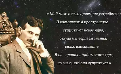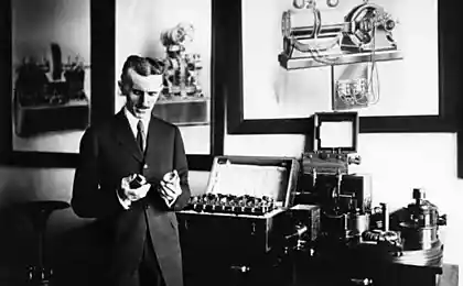
A few years ago, we - the authors of this material - pretty digging in patents, journals and lectures Tesla (fortunately, education allowed) concluded that the notorious Tower Tesla power transmission is not "fake", and it is working design.
As a result of several years of research, reflection, study of primary sources, data matching, screening and formation of hypotheses, etc. - There was a beautiful and, in fact, a simple model that strictly fit into the classical physics, and was confirmed by numerical simulation package Ansoft HFSS. Since the beginning of the project, we conducted a number of discussions in the various communities where we were required to "article for techies' - the result was this material.
This material is not a rigorous theory (ie, the theory that takes into account all the possible aspects of Tesla Tower). Nevertheless, we have tried to adequately illuminate the proposed concept and bring adequate numerical estimates of the main characteristics of the process. So if you are curious to understand the model and participate in a constructive discussion - we invite you to learn the material.
So, in our
scientific pop article described the beginning of the concept - in fact, the starting point of research (the formulation of which, by the way, it took a fair amount of time).
It is possible in a few sentences to describe the essence of the post below, labeled "attention - not for professionals." Then the essence could be formulated as follows: Tower creates a resonance current-voltage in a long line, where the long line (wire, one end connected to the master oscillator - ie the Tower) is taken the whole earth. Earth resistance is tiny (why - are analyzed below). Loss of electromagnetic radiation are also dramatic consequences, since "Rescues" the ionosphere from which perfectly reflects the low-frequency EM radiation and reflected - interacts with the Earth, again moving in the currents in a long line - Earth (model waveguide). And there is a stable pattern of standing waves current-voltage-charge in the ground, followed by a weak electromagnetic radiation between the Earth and the ionosphere.
I>
We started with the fact that the thoroughly studied the operation of the Tower Tesla following his records and patents. And this understanding has been born - what nat processes can cause this device to Earth, and this understanding - there was confidence that the proposed transfer of energy (and proven) by Tesla is possible. In this case, we start from the fact that the patent Tesla present all the fullness of description and not "hidden / hidden" parameters / processes. So that the "ideas", actively spread rumors and tabloid media - that Tesla using your Towers tried to "shake energy ether", use the "radiant energy", etc. - Believe journalists are only fantasies, far from physics. In our opinion, the work of the Tower completely fits in well-known physical laws, does not require any new concepts or had physical effects, and in this sense, our work (and future planned experiment) is purely applied nature - rather than the nature of basic research. If the material below is difficult to understand, you can read the article at the link above (it is written for the humanities, and contains a number of inaccuracies bordering incorrect, but gives a good qualitative understanding).
For symmetry, we proceed.
Tower Tesla: the characteristics of the work h4>
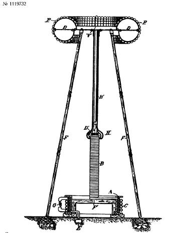
If you cut off the impossible, the Tesla Tower (less significant here is not technical nuances) is none other than the grounded one end of a helical quarter-wave resonator (characterized by distributed parameters), with additional capacity at the upper end of the helix. This cavity swinging master oscillator (sine wave frequency below 20 kHz - if we start from the Tesla patents, US787412 and US1119732 ).
In other words, the concept of the tower as follows:

Left shows the intimate physical capacity on top of the tower (in addition to self-capacitance of the coil), right - conventional equivalent circuit, where separately emphasized that capacity - solitary, ie formally - capacity between the tower and the infinite, and not between the tower and the Earth (because otherwise we get a banal LC-circuit closed through the ground). In order to minimize stray capacitance between the tower and the ground - that is, circuit LC-circuit towers across the land - it is obviously necessary to raise the capacity of the soil solitary (simple estimate shows that enough lift capacity at a height equal to the average diameter of a few tanks - in the performance of such conditions, the capacity between the tower and the Earth is reduced to a value comparable with own secluded container Tower).
As is known from classical electrical engineering, in such a cavity resonance mode capacitive and inductive reactance cancel each other, so that the generator "sees" only the resistance of the resonator. In a standing wave helix - with the node at the generator voltage and current loops of the same (in this case at the opposite end of the cavity - a node and an antinode of a current-voltage). Detailed analytical theory of operation of such a resonator can be seen for example here . If the material on this page is difficult to understand - that can be simplified without losing the essence: spiral resonator of this kind is nothing more than a quarter-wave long line , coiled - ie as in the "extended" line length in the resonator at the resonant frequency will be a standing-wave current voltage to a node voltage at one end of the line and the current node - at the opposite end; significant difference from the "extended" long lines - only enhanced inductive and capacitive coupling between adjacent sections of a line by virtue of their proximity to the geometrical configuration of the spiral, which is slightly (not drastically) - changes the resonance frequency and speed of propagation along the line.
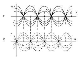
The figure - standing waves in a long line. Distribution of waves: a - voltage b - the current in the single-conductor line at different times (illustration from the сайта)
In other words, the Tower is a buffer charge - secluded capacity, wherein the predetermined power generator "drives" the charge of the land.
At the same time, EM radiation in the sense of radio waves (ie, in the far field, the wave zone tower) for our range of operating parameters - is virtually absent. We will demonstrate this.
In radio physics is the concept of spiral antennas, which, at first glance, can be correlated with the helical resonator. However, unlike the antenna electrical length of coil towers of 3-5 orders of magnitude smaller than the wavelength (i.e., number of turns in the thousands - despite the fact that the entire length of the winding is approximately equal to a quarter wavelength). Thus, most of the current (current antinode) is concentrated in the lower half of the tower. In other words, in terms of the external electromagnetic radiation, , this structure works as usual classical concentrated inductance i>. Ie conventional magnetic dipole.
Known formula that specifies the radiation resistance of an electrical short magnetic frame (magnetic dipole) with a wavelength λ (сопротивление radiation characterizes conductor loss by radiation of EM waves - ie the energy loss in the current radiation are considered as formal resistance, which is equal to the loss of radiation losses):

(formula 4.30 from the link above) i>
Where the equivalent length of the dipole l E sub> is related to the radius "a" frame ratio:

For the case of N turns formula is multiplied by a factor of N 2 sup> (for obvious reasons - the radiation energy density is proportional to the square of the amplitude of the field frame, ie, the square of number of turns in the frame).
Total,
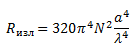
Substituting our parameters (frequency of 10 kHz, ie, the wavelength of 30,000 m, the radius of the coil - even 2 meters, the length of the winding - 10 km, the number of turns of about 800), we obtain the radiation resistance equal to 390 nano. That is negligible compared to the losses in the active resistance of the system (composed of at least units ohms).
But, in addition to the tangential component of the current in the resonator, and has an axial component (vertical resultant current) through which gives tower, including radiation conventional short electric dipole, whose radiation resistance is associated with dipole l Dina and wavelength λ as: < br />
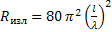
(formula 4.27 from the link above) i>
It is obvious that the axial component of the current as related to the wire diameter is tangential to the length of the coil turns. Ie approximately two orders of magnitude smaller tangential component (with coil diameter of 2 meters and the diameter of the conductor winding 2 cm). And, similar to the logic of accounting of number of turns, the effective resistance of radiation is reduced by the square of this value - ie 4 orders.
Thus, the effective radiation resistance (relative to the current flowing through the generator) with sufficient accuracy can be estimated as:
That our parameters (height of the tower is ten meters - let it be 20 meters for specifics) gives a value of about 35 nano, ie an order of magnitude smaller than the radiation from the tangential component of the current.
As a result, we see that both types of radiation (and the tangential and axial components of the current) are negligible with respect to losses in the active resistance of the circuit, despite the fact that it is the upper estimate (because for them the same amount of current is assumed all along the coil winding , while the current actually decreases sine - and "hot end" of the current node has a coil - i.e. zero current, and the actual radiation is a fraction higher ratings). So any ideas on what works as an antenna tower - are without absolutely no reason (at least, as long as we follow Tesla's patents and do not deal with fantasizing). Tower antenna is not in the classic sense - its radio emission (those. EM field in the future, the wave zone) is negligible, and all that it allows you to do - is to be an effective drive to charge that the generator plant removes from the soil at a frequency generator . So that the "genius" objections like "you have a conventional helical antenna - the efficiency of energy transfer is through the floor," and other "arguments" radio waves emanating from such a structure - only demonstrate a complete misunderstanding of the opponent the most basic concepts of radio physics.
From the tower understood, now go to the Earth h4>
For simplicity, let's start with the elementary analogies - from which gradually move on to the final concept.
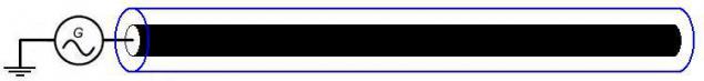
Suppose we have an electrically-long wire with a gap at one end, a second end grounded through the AC voltage source (electrical length - means that the length of the conductor is comparable to / greater than the wavelength of the generator based on the oscillator frequency and the speed of propagation of the wave - close to the speed light in vacuum):
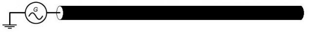
In such a long line, if line losses are small - a standing wave current-voltage (i.e., the superposition of the incident wave from the generator and the waves reflected from the free end of a long line). A typical example of such lines and such waves are conventional electric vibrators (I mean classical antenna), as shown in the figure below.
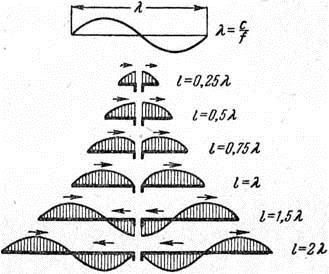
The distribution of current dipoles of different lengths. I>
The essence of the standing waves in a long line is quite simple to understand. You can mentally divide the whole wire into pieces half a wavelength. Each segment is the capacity (because the conductor has a distributed capacitance along it) and inductance (similarly). Accordingly, the standing waves is nothing more than a wave currents, charging such capacity - ie energy in a standing wave is alternately stored in the form of a charge distribution along the conductor (sine) - at which time the current is equal to zero, then a current distribution along the conductor (as well sine) - and at that point the surface charge density along the the conductor is zero. Which essentially repeats the normal mode LC-circuit (inductor connected in series with a capacitance capacitors), but taking into account the distributed nature of capacitance and inductance. Half-wave currents in the "flocking" to the center of the selected segment - creating antinode voltage (ie, the appearance of the surface charge on the conductor), and in the next segment of "spread" of a similar center - creating a charge of opposite sign, then this process is repeated (as opposed to direction - creating opposite charges on the surface of the conductor). Of course the above applies to the ideal line (lossless) open at the end, in line with the real losses (and / or line load on the end) process is more complicated - but the fundamental essence remains the same.
If the transition to elementary mechanical analogy, the process will be the closest of the compression wave-stretching in the length of the spring, occurs when a spring (lying on a support with zero friction) are beginning to swing back and forth along the axis of the spring at one end of the spring - when a second fixed end. In this current - corresponds to the velocity of the corresponding portion of the spring, and voltage - corresponds to the degree of compression of the spring. Ie at some point in time all parts of the spring will have zero velocity - and the degree of stretching of the spring will change the sine along it (such things alternating clots and discharge) - which corresponds to zero current in the standing wave at the same time the maximum voltage (ie, the maximum surface the charge density on the conductor), and at another time - a quarter of the oscillation period - on the contrary, all spring would not be deformed, but its instantaneous velocity plots will change along the axis of the sine of the spring (which corresponds to the zero point charge density along the conductor of a long line - but the maximum current in it).
Losses for this situation can be broadly divided into two components: the ohmic losses and radiation losses.
In the case of a large length of the conductor, and his small ohmic resistance, the main contribution to the loss will produce radiation (ie, radiation resistance).
As you know, if we surround a grounded conductive shield line, the radiation losses will be offset, and this structure is called coaxial waveguide - and, in our example, the wave in a coaxial waveguide will exist as a TEM mode (port excitation in this case, in fact, a generator connected via the ground - to the inner and outer conductors of the waveguide).
In fact, the mode TEM mode can be interpreted as a mode of inductive coupling the inner and outer conductors of the waveguide through a field of near-field currents on these conductors (current change in the inner core - is respectively EMF on the external screen, and the induced current on the external screen is directed against change current on the inner conductor - i.e. essentially conventional induction current in the near field) so that the transverse flow of energy is not zero in a time average (for TM or TE modes), but zero at any one time. There is no reflections from the boundaries of the waveguide - the flow of energy is only longitudinal in nature (ie, directed along the axis, and thus Poynting vector is directed as strictly parallel to the direction of wave propagation - along the axis of the coaxial resonator).
Therefore, the mode TEM mode in the coaxial waveguide is characterized by good parameters (relative modes TE or TM modes) in terms of energy transfer and the smallness of the wave damping coefficient in the waveguide, and if necessary, the transfer of energy through a coaxial waveguide - as a rule, tend to use it TEM mode -mode.
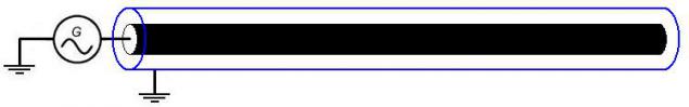
However, even if we remove the grounding of the outer shield of the waveguide along the entire length of the screen in addition to its end sections - the screen is perfectly fulfill its function.
Indeed, such a screen in any case, there is a long line, as a generator to which acts of EMF from the AC on the inner conductor-conductor. And only at the edges of the screen - due to a very small capacity of the edges, there will be some voltage antinode, and throughout the rest of the length of the screen - it will function properly. Which is confirmed by elementary simulation in HFSS.
Further, what happens if we do not just remove the grounding external screen - but "we close" edge as shown in the figure below (so that the external display will be a sort of "capsule")? The answer is quite clear - this situation will not be different from the above.
href="http://books.google.ru/books?id=nsJDiwt3lW4C&pg=PA253&lpg=PA253&dq=Amplitude+of+Schumann+resonance+modes&source=bl&ots=O7QSCdM0te&sig=3HnsQk4AZRQAJDmhlol6ayEP9tQ&hl=ru&sa=X&ei=nZGcUryxNLLn4QSEzYGwBw&ved=0CF4Q6AEwBQ#v=onepage&q=Amplitude%20of%20Schumann%20r">вот
резонанса
Because
Ie
Ie
Ie
Ie
I>
I>
I>
Ie
I>
I>
I>
Ie
I>
very much.
I>
I>
I>
I>
I>
I>
Ie
I>