1515
The use of self-made thermal-based Arduino research energy saving
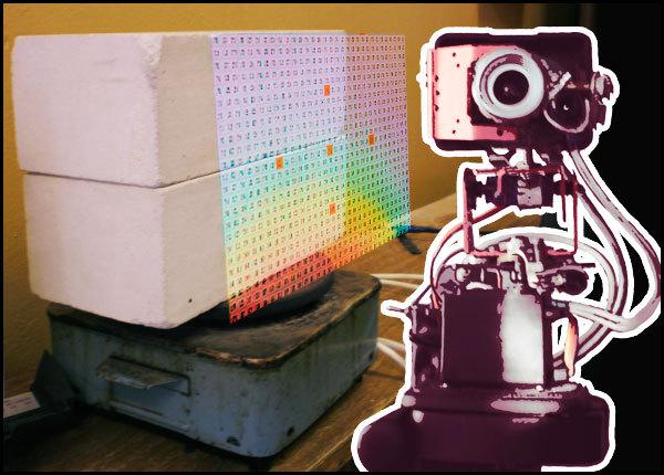
What can be done with two bricks, tiles and an ordinary electric Imager on Arduino ? I save a lot of electricity! As all these things are interconnected, can be found in this article. Along the way, I had to address some things from TAU (automatic control theory), but I tried to get rid of boring mathematics and explain in detail the role of the "thermal imager for less than $ 100" in the process.
Attention! Under the cut, there is one very "fat", but a pretty picture! And a lot of text!
Today, almost everyone in the household has electric heaters - tiles, kettles, heaters and boilers well, at worst. In general, the principle of their work can be described as - the current flows through the nichrome filament and causes it to heat, as well as robust design shakes meter. All heaters are so many "eat" electricity, so happened. However, there is a way out!
The fact that every body has its own "thermal inertia", and you can bring may not be entirely accurate, but it is understood the analogy of a large circular cobblestone:
Imagine that you need to roll back the cobblestone at a distance of ten meters. You can immediately pounce on him all the weight, throughout the region there are forces that push and thus move it to the desired location. A first effort can move it, and then slightly push. Of course, in the second case, we get tired less. So the first way of analogy - it is the inclusion of the heater directly into the network, and the second - the use of energy-efficient control algorithms.
This means that we can apply the input voltage of the electric heating element of special form, which will reach the desired temperature, but with less power (kWh). Naturally, this saving is not taken from the air. And there it is due to increase in the heating time, and the more time - the correspondingly greater savings! How to calculate this operation - has a long history, and in this article it will be affected only superficially (for Matan).
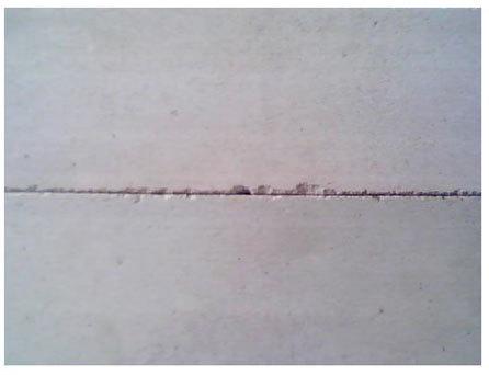
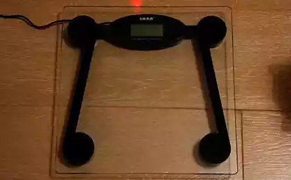
So, let us take, for example, to study common stove-top, with a capacity of 1 kW. And put her two silicate brick - to raise the same "thermal inertia" (as you have already understood what this notional value of the longer, the more grandiose percent savings). Here is a beauty:
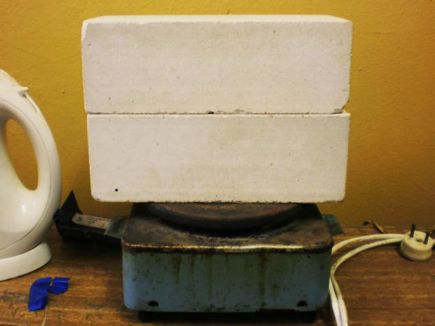
I agree, it does not look! She has seen a lot in his life, and yet continue to serve in the name of science, and more.
To calculate the energy-saving control for the electric heaters in the first place, it is necessary to perform the task of drawing up its simplest mathematical model. It can be, for example, by a differential equation, or, as in this case, the transfer function. In the language of Wikipedia, the transfer function is a differential operator, expressing the connection between the input and output of a linear stationary system. And knowing the input signal and the transfer function of the system, it is possible to restore the output.
In electric heaters input value is действующее voltage , and the output - the temperature of the object. And having the thermal transfer function of the object, we can, by submitting to the input voltage of 220V, the output is the temperature, and thus possess a true mathematical model.
Opening any textbook on TAU, we can see that the transfer functions of species there are so many. So how do you know which one is most accurately describe the object of study? This requires a kind of "recognition" for the Scientific - Identification of the facility. It sounds serious, and in practice is as follows: To enable the network and to measure the temperature throughout the entire heating time. That's what happens in the case of hobs:
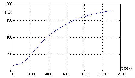
Based on the form of the function, you can safely conclude that the stove is accurately described by the transfer function, called second order aperiodic link i>. That's how it looks:
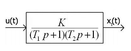
Here, the input value U (t) denotes the voltage which can be a constant in time (220, refers to the effective value) and changing by any above law. The output value x (t) - the temperature. From the pictures you can see that at this level has its own parameters - K, T1 and T2, which are called the gain and time constant. As their name implies, the K value represents the amount of change of the signal transmitted through a link, and the time constants are directly dependent on the same "thermal inertia" of the object. These factors can be estimated from the previous schedule. And, obviously, that they affect the accuracy of the mathematical model, and hence an amount of energy saved.
I'll tell you - this tiles for more than one year, students counted the most energy-saving control (why it's so shabby). And time after time, to identify the object (well, to get the chart above) a thermocouple strictly in the middle between the bricks. So the natural question arose - and that if you take and move the temperature sensor in a very different place, how to change the parameters of the object? Each time a different experience to hold the position of thermocouples would be extremely long - as can be understood from the graph above, an experiment is nearly three hours. And then at the time the most suitable use of the thermal imager in the Arduino.
The main drawback of the device just mentioned - a long time imaging in the infrared is practically no role - the experiment is very long compared to the time of scanning. But as a result, it turns out not one graph of temperature change in one point as much as 768! In accordance with a resolution of 32x24 pixels thermogram.
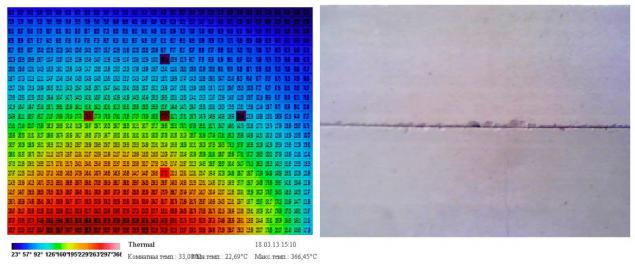
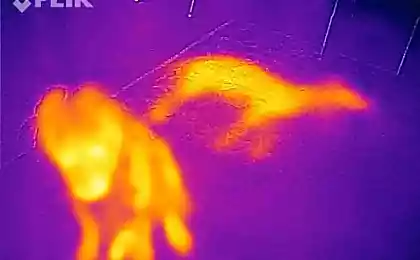
Thus, by using a thermal imager, a similar experiment was carried out on the identification of the object - 25 thermal images were filmed for several hours. Scanning area covers almost the entire lateral surface of the bricks, as shown in the picture:
But so is the process of heating in the infrared (IR sort of time-lapse):
It is worth noting that the false color in the thermal image are assigned automatically depending on the maximum and minimum measured temperature, and the gradient of compliance and dynamically changing.
The discovery was the fact that the center of the heating shifted to the left, even though the camera is pointing straight down the middle bricks. This is probably due to inhomogeneities within the lower brick or tile design of the heating element.
Thermal-based Arduino works as follows - first component of the spatial matrix temperatures, then it has already rendered in a false color image. This proved a huge plus - because the output of the system is not just a pretty picture but the image matrix, which plays a major role in the study. Taking at random points on five of these matrices (of 25), it is possible to trace the dynamics of change of temperature:
That's graphics will look transients (such as temperature versus time are called) in five selected points and a thermocouple for comparison:
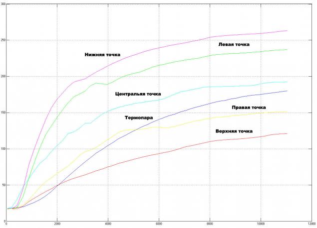
Charts with a thermal imager clumsy as just simply based on 25 points, while data from the thermocouple comes every two seconds. In addition, the naked eye can notice the difference in the charts with a thermocouple and temperature of the thermal imager. Perhaps this is due to the physical differences of methods of measurement - if the thermocouple is located, as it were "inside" object, the thermal infrared sensor scans the surface of it, which in turn affect the processes of evaporation of moisture and air convection.
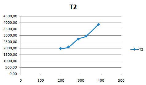
Further, from these graphs, you can get the best coefficients (K, T1 and T2) to create a mathematical model of electric. But this time, we will have not one, but six models!
Omitting the mathematical part of it is worth noting that in the course of the study was seen interesting feature - the coefficients depend on the location of the point on the thermogram regarding the proposed center heating - this is the red area at the bottom of the thermogram. And their relationship is almost linear:
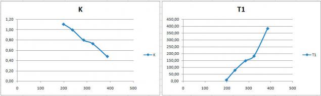
And since we know that the graphs do not lie, focusing on the position of the measuring point, in principle, it is possible to determine the coefficients for almost every point of the object, without resorting to the construction schedules for all 768.
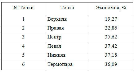
Nevertheless, one of the five selected points previously, the best results in energy savings showed the left point. As part of the system controller that is configured based on data received from this point:
The percentage of savings is considered to be compared with the energy spent on heating is electric to 80 degrees by simple inclusion into the outlet. How should change the voltage on a hotplate to save nearly 40% of the electricity, you can look at this chart:
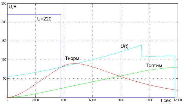
Here, the optimal control is indicated by U (t), corresponding to the temperature of the tiles in this administration - T (FINE). For comparison, the graphs of voltage and temperature of the tiles by simple inclusion into the network. As you can see, the savings obtained by increasing the heating time is almost three times.
To summarize:
So, if you are full article tormented by the question, why do you need to heat the bricks on the stove and read what that mythical savings if, in practice, no one needs, then here's a decent answer: the fact that the tiles is a direct analogue of the object of study as an oven resistance. This industrial monster capacity of 800 kW (for example) not only consumes a lot, but a lot of electricity dramatically. And, accordingly, energy efficiency is very out of place.
The thermal imager in this case, played a huge role, allowing to build the most complete picture of the processes occurring during operation of electric appliances, and on the basis of these data to get more accurate in terms of energy-saving model of the object, and, moreover, to find finally serious application as a complete unit .
Source: habrahabr.ru/post/226313/

Attention! Under the cut, there is one very "fat", but a pretty picture! And a lot of text!
Today, almost everyone in the household has electric heaters - tiles, kettles, heaters and boilers well, at worst. In general, the principle of their work can be described as - the current flows through the nichrome filament and causes it to heat, as well as robust design shakes meter. All heaters are so many "eat" electricity, so happened. However, there is a way out!
The fact that every body has its own "thermal inertia", and you can bring may not be entirely accurate, but it is understood the analogy of a large circular cobblestone:
Imagine that you need to roll back the cobblestone at a distance of ten meters. You can immediately pounce on him all the weight, throughout the region there are forces that push and thus move it to the desired location. A first effort can move it, and then slightly push. Of course, in the second case, we get tired less. So the first way of analogy - it is the inclusion of the heater directly into the network, and the second - the use of energy-efficient control algorithms.
This means that we can apply the input voltage of the electric heating element of special form, which will reach the desired temperature, but with less power (kWh). Naturally, this saving is not taken from the air. And there it is due to increase in the heating time, and the more time - the correspondingly greater savings! How to calculate this operation - has a long history, and in this article it will be affected only superficially (for Matan).
So, let us take, for example, to study common stove-top, with a capacity of 1 kW. And put her two silicate brick - to raise the same "thermal inertia" (as you have already understood what this notional value of the longer, the more grandiose percent savings). Here is a beauty:

I agree, it does not look! She has seen a lot in his life, and yet continue to serve in the name of science, and more.
To calculate the energy-saving control for the electric heaters in the first place, it is necessary to perform the task of drawing up its simplest mathematical model. It can be, for example, by a differential equation, or, as in this case, the transfer function. In the language of Wikipedia, the transfer function is a differential operator, expressing the connection between the input and output of a linear stationary system. And knowing the input signal and the transfer function of the system, it is possible to restore the output.
In electric heaters input value is действующее voltage , and the output - the temperature of the object. And having the thermal transfer function of the object, we can, by submitting to the input voltage of 220V, the output is the temperature, and thus possess a true mathematical model.
Opening any textbook on TAU, we can see that the transfer functions of species there are so many. So how do you know which one is most accurately describe the object of study? This requires a kind of "recognition" for the Scientific - Identification of the facility. It sounds serious, and in practice is as follows: To enable the network and to measure the temperature throughout the entire heating time. That's what happens in the case of hobs:

Based on the form of the function, you can safely conclude that the stove is accurately described by the transfer function, called second order aperiodic link i>. That's how it looks:

Here, the input value U (t) denotes the voltage which can be a constant in time (220, refers to the effective value) and changing by any above law. The output value x (t) - the temperature. From the pictures you can see that at this level has its own parameters - K, T1 and T2, which are called the gain and time constant. As their name implies, the K value represents the amount of change of the signal transmitted through a link, and the time constants are directly dependent on the same "thermal inertia" of the object. These factors can be estimated from the previous schedule. And, obviously, that they affect the accuracy of the mathematical model, and hence an amount of energy saved.
I'll tell you - this tiles for more than one year, students counted the most energy-saving control (why it's so shabby). And time after time, to identify the object (well, to get the chart above) a thermocouple strictly in the middle between the bricks. So the natural question arose - and that if you take and move the temperature sensor in a very different place, how to change the parameters of the object? Each time a different experience to hold the position of thermocouples would be extremely long - as can be understood from the graph above, an experiment is nearly three hours. And then at the time the most suitable use of the thermal imager in the Arduino.
The main drawback of the device just mentioned - a long time imaging in the infrared is practically no role - the experiment is very long compared to the time of scanning. But as a result, it turns out not one graph of temperature change in one point as much as 768! In accordance with a resolution of 32x24 pixels thermogram.
Thus, by using a thermal imager, a similar experiment was carried out on the identification of the object - 25 thermal images were filmed for several hours. Scanning area covers almost the entire lateral surface of the bricks, as shown in the picture:

But so is the process of heating in the infrared (IR sort of time-lapse):

It is worth noting that the false color in the thermal image are assigned automatically depending on the maximum and minimum measured temperature, and the gradient of compliance and dynamically changing.
The discovery was the fact that the center of the heating shifted to the left, even though the camera is pointing straight down the middle bricks. This is probably due to inhomogeneities within the lower brick or tile design of the heating element.
Thermal-based Arduino works as follows - first component of the spatial matrix temperatures, then it has already rendered in a false color image. This proved a huge plus - because the output of the system is not just a pretty picture but the image matrix, which plays a major role in the study. Taking at random points on five of these matrices (of 25), it is possible to trace the dynamics of change of temperature:

That's graphics will look transients (such as temperature versus time are called) in five selected points and a thermocouple for comparison:

Charts with a thermal imager clumsy as just simply based on 25 points, while data from the thermocouple comes every two seconds. In addition, the naked eye can notice the difference in the charts with a thermocouple and temperature of the thermal imager. Perhaps this is due to the physical differences of methods of measurement - if the thermocouple is located, as it were "inside" object, the thermal infrared sensor scans the surface of it, which in turn affect the processes of evaporation of moisture and air convection.
Further, from these graphs, you can get the best coefficients (K, T1 and T2) to create a mathematical model of electric. But this time, we will have not one, but six models!
Omitting the mathematical part of it is worth noting that in the course of the study was seen interesting feature - the coefficients depend on the location of the point on the thermogram regarding the proposed center heating - this is the red area at the bottom of the thermogram. And their relationship is almost linear:


And since we know that the graphs do not lie, focusing on the position of the measuring point, in principle, it is possible to determine the coefficients for almost every point of the object, without resorting to the construction schedules for all 768.
Nevertheless, one of the five selected points previously, the best results in energy savings showed the left point. As part of the system controller that is configured based on data received from this point:

The percentage of savings is considered to be compared with the energy spent on heating is electric to 80 degrees by simple inclusion into the outlet. How should change the voltage on a hotplate to save nearly 40% of the electricity, you can look at this chart:

Here, the optimal control is indicated by U (t), corresponding to the temperature of the tiles in this administration - T (FINE). For comparison, the graphs of voltage and temperature of the tiles by simple inclusion into the network. As you can see, the savings obtained by increasing the heating time is almost three times.
To summarize:
So, if you are full article tormented by the question, why do you need to heat the bricks on the stove and read what that mythical savings if, in practice, no one needs, then here's a decent answer: the fact that the tiles is a direct analogue of the object of study as an oven resistance. This industrial monster capacity of 800 kW (for example) not only consumes a lot, but a lot of electricity dramatically. And, accordingly, energy efficiency is very out of place.
The thermal imager in this case, played a huge role, allowing to build the most complete picture of the processes occurring during operation of electric appliances, and on the basis of these data to get more accurate in terms of energy-saving model of the object, and, moreover, to find finally serious application as a complete unit .
Source: habrahabr.ru/post/226313/


In the network appeared Picture a man, who was expelled from Saudi Arabia for its beauty
Google has become a domain registrar