522
On the basis of modules, Master kit to create the electrical system for the bike
The Cycling season has already begun, and many cyclists began to visit the idea of creating an onboard network for the bike. What would Cycling be able to use the flashlight, turn signals, brake lights or music system and not only while driving. And besides, it would be the ability to charge your phone, smartphone or camera. Here one of such letters: "Hello. Offer you a product idea for a topic, auto-Moto-velo (although he clearly led, of course). This is a universal charger for recharging batteries and power light elements on bikes with generators. The problem is that while stationary the whole light goes out, because there is no discharge. This device must be connected to a Dynamo, to be able to recharge a small battery to show its charge level, and of course to power the motion lights."
Ready device we have, but in this article we will explain how on the basis of modules, Master kit, you can create electrical system for the bike.

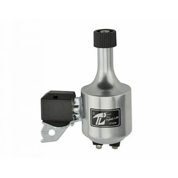
As a source take a regular bike generator "bottle" type, such as a universal:
For minimum on-Board network, we need three modules. It BM037, and PW810 NT800.

BM037 is a pulse step-down DC/DC Converter. In the diagram it will be used as a rectifier to convert the AC voltage simple Bicycle generator, "bottle" type, a DC voltage. If necessary, instead of this module, you can use a diode rectifier with an electrolytic capacitor of large capacity.
PW810 is pulsed universal DC/DC Converter. The module is capable both of decrease and increase the input voltage. As the generator during the motion is unstable output voltage, it is highly dependent on speed, with the help of this Converter we will get a stable voltage.
When using these two devices we will be able to get a stable output voltage from 5V to 12V. The required voltage is set using the knob on the PW810. But with this enabled, when visiting on-Board network will disappear produced by the voltage generator. That would not have been necessary to Supplement the scheme with battery NT800. This integration will allow to use the onboard network in stops and will increase the capacity of the system, which will allow to connect more devices. And in the process of movement on the bike will be the battery charging process.
In addition, the article says: Instead of NT800, you can use any you have on hand battery with an operating voltage of 3.7 V, 6V or 12V.
The wiring modules can be seen in the figure below:
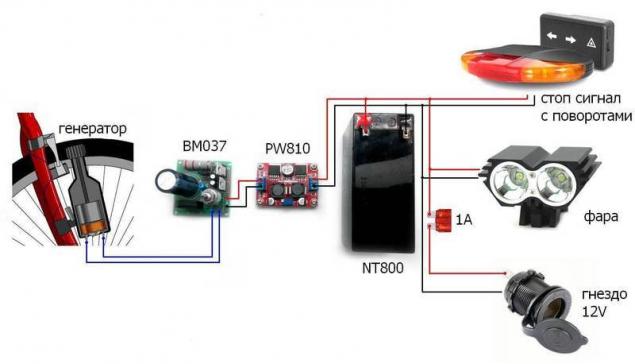
It was not difficult. It can be chanted by anyone, even unfamiliar with electronics. Setting the scheme does not cause any difficulty. Connect the laboratory power supply instead of generator or spin the wheel on which you installed the generator. Now, with the help of the voltage regulator module BM037 necessary to limit the maximum output voltage up to 26V. Using the voltage regulator module PW810, you need to set the output voltage of battery used in our case 13.8 V. Now print the cable from the battery to the necessary outlets, such as the type of automobile cigarette lighter, and use any favorite gadgets without worrying that they will run out at the most inopportune moment.
If you need to have in the vehicle electrical system is not a standard voltage lower than 12V, for example 5V or 2.4 V. this can be connected to the terminals of the battery step-down DC/DC Converter PW841:
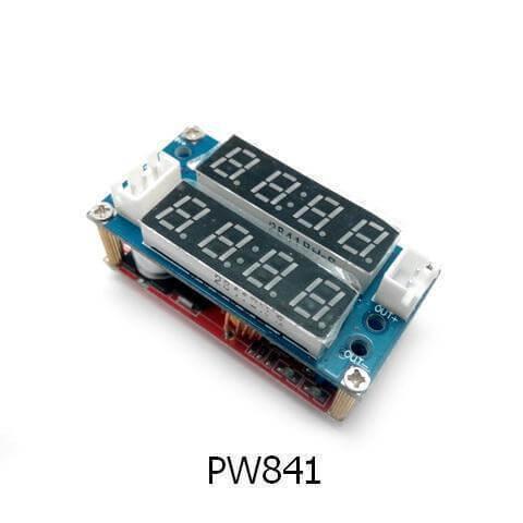
This Converter is equipped with two displays, the top to display the output voltage, the bottom to display the power consumption. This will allow you to monitor status and current consumption of connected devices.
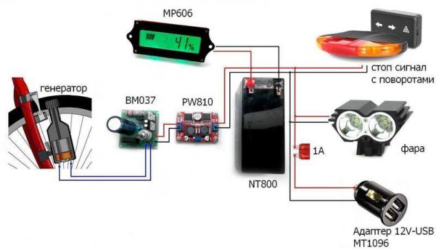
If desired, battery can be equipped with a control module of the charge MP606:
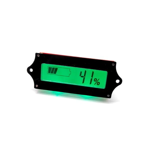
The module is connected parallel to the battery terminals. Despite the fact that the module has very low power consumption, 10 mA, long-term Parking are encouraged to consider disabling it. This module can be useful in any other technique where you use a battery, for example a scooter, car, etc.
Then the final version will look like according to the scheme:
published
P. S. And remember, only by changing their consumption — together we change the world! ©
Join us in Facebook , Vkontakte, Odnoklassniki
Source: geektimes.ru/company/masterkit/blog/274701/
Ready device we have, but in this article we will explain how on the basis of modules, Master kit, you can create electrical system for the bike.

As a source take a regular bike generator "bottle" type, such as a universal:

For minimum on-Board network, we need three modules. It BM037, and PW810 NT800.

BM037 is a pulse step-down DC/DC Converter. In the diagram it will be used as a rectifier to convert the AC voltage simple Bicycle generator, "bottle" type, a DC voltage. If necessary, instead of this module, you can use a diode rectifier with an electrolytic capacitor of large capacity.
PW810 is pulsed universal DC/DC Converter. The module is capable both of decrease and increase the input voltage. As the generator during the motion is unstable output voltage, it is highly dependent on speed, with the help of this Converter we will get a stable voltage.
When using these two devices we will be able to get a stable output voltage from 5V to 12V. The required voltage is set using the knob on the PW810. But with this enabled, when visiting on-Board network will disappear produced by the voltage generator. That would not have been necessary to Supplement the scheme with battery NT800. This integration will allow to use the onboard network in stops and will increase the capacity of the system, which will allow to connect more devices. And in the process of movement on the bike will be the battery charging process.
In addition, the article says: Instead of NT800, you can use any you have on hand battery with an operating voltage of 3.7 V, 6V or 12V.
The wiring modules can be seen in the figure below:

It was not difficult. It can be chanted by anyone, even unfamiliar with electronics. Setting the scheme does not cause any difficulty. Connect the laboratory power supply instead of generator or spin the wheel on which you installed the generator. Now, with the help of the voltage regulator module BM037 necessary to limit the maximum output voltage up to 26V. Using the voltage regulator module PW810, you need to set the output voltage of battery used in our case 13.8 V. Now print the cable from the battery to the necessary outlets, such as the type of automobile cigarette lighter, and use any favorite gadgets without worrying that they will run out at the most inopportune moment.
If you need to have in the vehicle electrical system is not a standard voltage lower than 12V, for example 5V or 2.4 V. this can be connected to the terminals of the battery step-down DC/DC Converter PW841:

This Converter is equipped with two displays, the top to display the output voltage, the bottom to display the power consumption. This will allow you to monitor status and current consumption of connected devices.
If desired, battery can be equipped with a control module of the charge MP606:

The module is connected parallel to the battery terminals. Despite the fact that the module has very low power consumption, 10 mA, long-term Parking are encouraged to consider disabling it. This module can be useful in any other technique where you use a battery, for example a scooter, car, etc.
Then the final version will look like according to the scheme:

published
P. S. And remember, only by changing their consumption — together we change the world! ©
Join us in Facebook , Vkontakte, Odnoklassniki
Source: geektimes.ru/company/masterkit/blog/274701/


