3182
Subtle complexity of rocketry, Part 4: More about the engines and tanks
Diverse and unpleasant tribute to be paid imperfection of our world developers of missile technology. Today we'll talk about what to pay for the increase in the parameters of liquid jet engines and those subtle problems that designers are waiting tanks.
Schemes of work LRE h4>
The existence of different schemes, allowing developers to choose the right, with the desired qualities (ease of use, ease of production, high thrust and high specific impulse) and acceptable deficiencies.
Size exclusion feed h5>
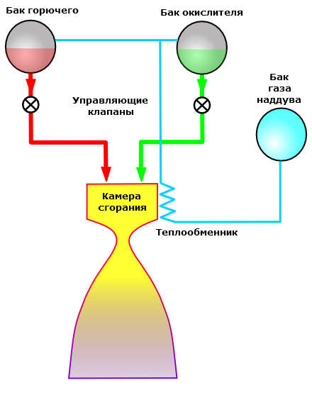
The easiest option. Pressure gas pressurization (first nitrogen was now massively switched to helium) provides the necessary parameters of the inlet pressure to the engine. On the exclusion of wire feeding the first rocket experiments GIRD and Goddard but it has not gone over time from the scene. This scheme is used in the propulsion of satellites and spacecraft. "Union", "Shuttle", "Apollo" used it. Especially good supply of exclusion combined with a pair of fuel UDMH / AT due to its self-ignition. It turns a simple, reliable engine with the possibility of multiple inclusion.
Advantages:
Easy. Reliability. The cheapness. No loss of mass on the turbopump assembly. High efficiency for small engine thrust Weaknesses: 
Low specific impulse. Poorly suited to high-thrust engines.
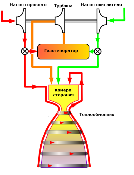
Open circuit h5>
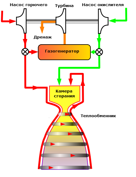
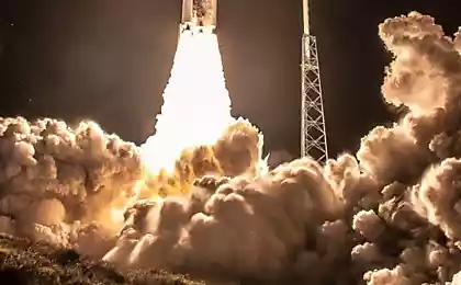
To improve traction, specific impulse and engine power has needed a pump. The required parameters can only provide turbine. In the first "real" missiles - "V-2", "R-7" to drive a turbine to use a separate working medium - concentrated hydrogen peroxide, but then switched to burning a small fraction of the fuel components. Exhaust gas generator at first simply thrown to the side, a very spectacular torch:
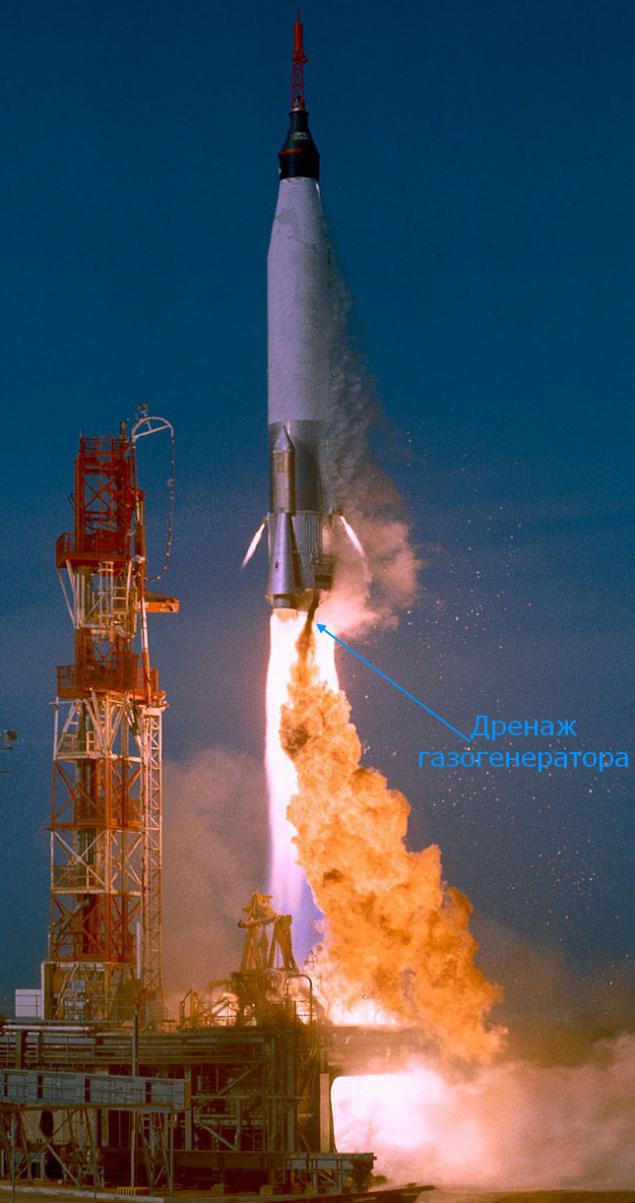
Starting "Atlas". Note the size and color of the flame output. Clearly shows that TNA runs on excess fuel that burns in the air. I>
Drainage generator gas directly overboard looked wasteful, so he began to be sent to the supercritical part of the nozzle - and a bit of UI to add, and as завеса work:
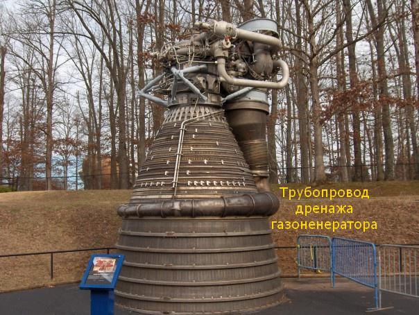
The classic picture - the engine of an F-1 i>
However, the drainage of the gas generator open circuit has another interesting use case - the engine roll control:
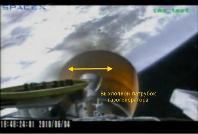
The second stage rocket Falcon-9. Rotate exhaust pipe leads to the swirl force that controls the roll stage. I>
View dynamics (third minute)
Open circuit is used now and unlikely to disappear in the near future. Due to the relatively small loss of IAs it allows you to make a more powerful engine (F-1) or a cheaper engine ( RS-68 ) or to make it possible to develop for the team with limited resources (Merlin).
Advantages:
It is easier and cheaper than a closed circuit. Weaknesses: 


The lower specific impulse than in a closed circuit.
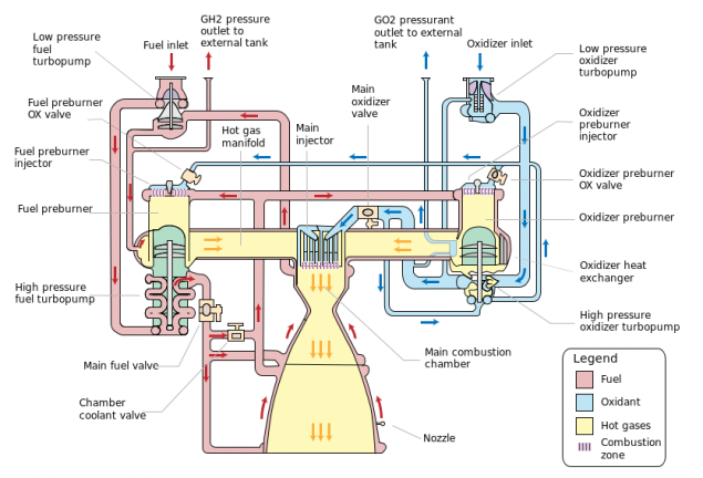
Closed circuit h4>
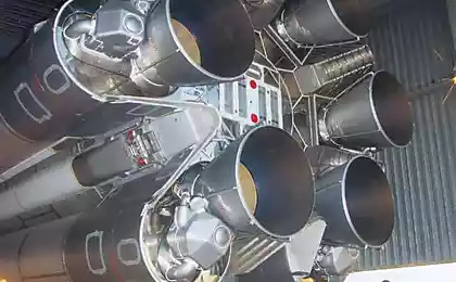
The logical solution to improve the UI engine was an attempt to direct the exhaust gas generator into the combustion chamber so that it burned down in the best conditions to produce thrust. This task proved to be quite difficult - in the combustion chamber of a lot of pressure, there are additional issues of sustainability of the engine because it adds one more feedback "TNA-combustion chamber." Engines closed circuit first started doing the USSR - NK-15 and NK-33 were put on a heavy rocket H-1, RD-253 operates on the "Proton". US late enough do this scheme - the first LRE closed circuit became the US space shuttle main engine SSME, which, on the other hand, was the first closed-cycle engine on a pair of oxygen / hydrogen.
Admire the complexity of the engine 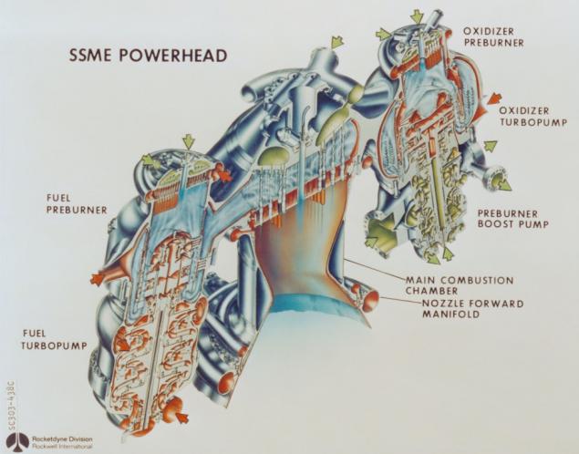
Advantages:
The greatest UI. Weaknesses: 


The most difficult and expensive scheme.
Driving with a phase transition h4>
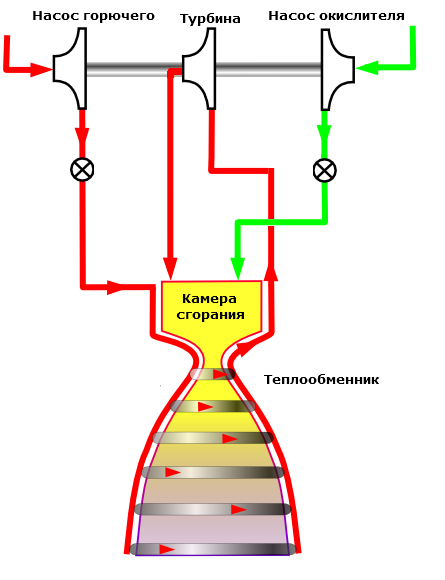
Elegant "hack" of physics rocket engine - the need to cool the engine nozzle is used as an energy source for the turbopump unit. The scheme was devised for the engine RL-10, which for fifty years is used in the boost block "Centaurus».
Advantages:
No loss of mass on TNA. The simplicity of design. Reliability. Weaknesses: 
Suitable only for oxygen-hydrogen pairs. The pressure is lower than in the circuit with TNA, therefore, MI below.
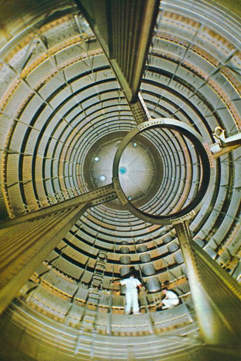
The insides of tanks h4>
Inside the tank launcher too many interesting things. Tanks are one above the other, so you must supply lines "upper" component pipelines boost, as well as, perhaps, it is necessary to solve the problem of finding the next fuel components with different temperatures. And then there is the problem of fluctuations in fuel, which also must be addressed.
Piping Components h5>
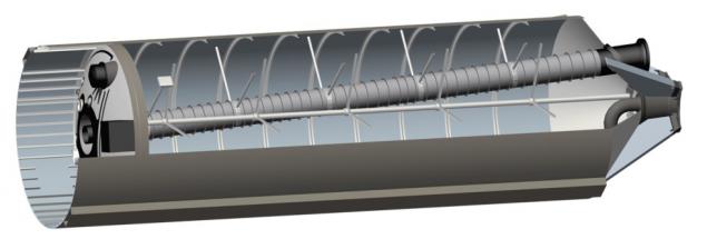
This - fuel tank (bottom) of the first stage of the rocket "Soy-2.1V." Note the large pipe with a corrugated sheath. This - the pipeline oxidant. Since the oxidizer is liquid oxygen, it is necessary to place insulation, to the trumpet not namerz kerosene. Alas, all this requires additional mass.
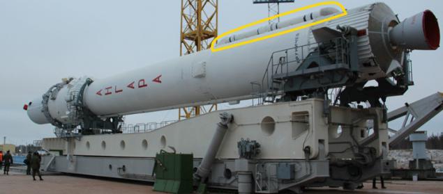
And this is - PH "Angara". Highlighted in yellow - a pipeline that performs the same function. Based on the proportions, it is also the conduit oxidant (oxygen tanks more kerosene for the pair oxygen-kerosene), but printed side to simplify and reduce the cost of production. On the one hand, it is unsightly, but digital control system to cope with asymmetric missiles.


intertank compartment h5>
The second and third stage of the rocket "Saturn-V» was used very elegant solution - oxygen and hydrogen tanks have a common wall:
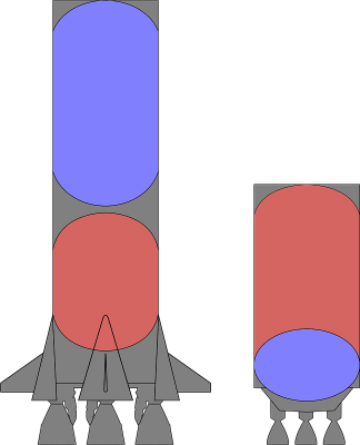
On the left - the first step to intertank compartment, on the right - the second stage with a common wall. Red - fuel, blue - oxidant. I>
The difficulty was the fact that the liquid hydrogen and oxygen, the temperature difference was 70 degrees Celsius. Therefore, the panel consisted of two layers of aluminum with insulation in between. This design allows to save as much as 3, 6 tons of the second stage. Curiously, the fuel tank "Space Shuttle" was in some ways a step back, it was a classic intertank compartment.

Piping pressurization h5>
If you have deployed SSME diagram above, we saw there exits gasified hydrogen and oxygen. They were used to supercharge the respective tanks. On the one hand, the weight saved in separate tanks of gas turbocharging, on the other hand, received an additional pipeline:
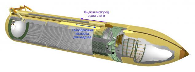
Эта Big same picture.

damping partition h5>
If you take a close look at the pictures of sections of tanks, then saw the ring of varying width and cross at the bottom of the shuttle tanks. This - special elements for vibration damping fuel.
Crossings at the bottom of the fuel tank of the shuttle used to prevent the formation of funnel for emptying the tank. The fact that the funnel can be sucked to lead gaseous fuel component, which can cause problems in the piping and engines.
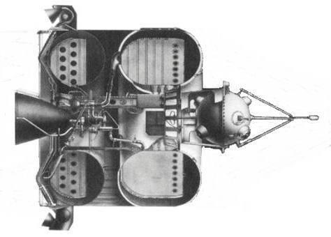
Annular elements serve to dampen the vibrations of fuel. Since it is a liquid, the overflow fuel to one side when maneuvering may cause problems for system stabilization. Partitions can be very large, as the first stage of "Saturn-I»:
Or virtually absent, as in the third stage of "Saturn-V»:
the form of long, but I recommend to look - very interesting seen behavior liquid hydrogen rocket during acceleration and weightlessness. I>
The general rule is - the more maneuvers expected from the stage, the greater the size of the partition is placed. For example, the Soviet bloc "E" - the third stage rocket "Vostok". There partition size in almost the entire height of the tank, because the unit can actively maneuver, and you can not afford to splash fuel:
And all this, alas, the additional cost mass.

System emptying tanks and synchronization h5>
Another problem that must be addressed. Firstly, each combustion engine in something unique. Necessarily small spread thrust and flow rate of the fuel components. Even for a single engine should be put a special system to run out of fuel and oxidant simultaneously. And if we have a few tanks or side steps, you have to put a special system which will ensure the simultaneous completion of the components in several stages. Now this system is called more fuel management system and consists of a set of level sensors and a digital computer, which, in addition to missile control, solves this problem and more:
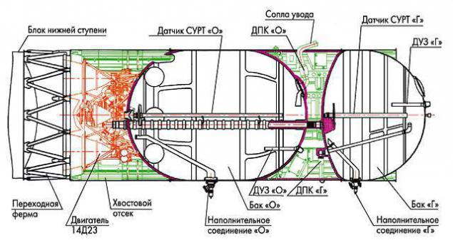
The third stage of "Soyuz". Along the axis of the tanks are level sensors for Surt. I>
However, despite the efforts of Surt, she herself has limited accuracy, and some small fraction of the fuel is still lost. Her take into account when filling by adding so-called "Guaranteed supply of fuel».

Epilogue h5>
Recommend to watch the show «Moon Machines» (русская version , English version ). Very good and illustrated the complexity that must be addressed in the design of space technology.
To navigate:
The first article of the cycle. The second article - solid motors. third article - types of liquid fuel, geometric dimensions, transportation. Source: habrahabr.ru/post/215959/


The most terrible toy.
Video review of the functions of "smart" Samsung Gear 2 hours and fitness bracelet Gear Fit