I want to tell you about my idea and how I tried to translate it into practice. The device is an amplifier of leg muscles (ankle), who works on the principle of energy storage in the spring. In this article I tried to explain all the way, which took place. I also want to say that this was my first experience in dealing with the actual construction of, and this is my graduation project.
Idea h4> When I was a student MSTU. Bauman, acrobatics, and generally liked difficult coordinating sports (and still love). Around 2007 I found on the internet device that helps a person to jump high and run. Its name JollyJumper . In fact, it consists of a spring rigidly attached to the ankle person. In this case, the ankle (foot relative to the tibia and metatarsus) is firmly fixed.
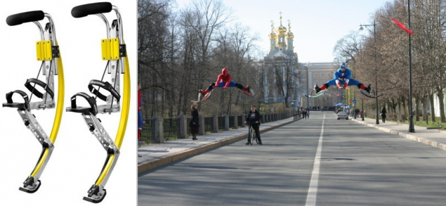
This variant design can be called an analogue of the trampoline. The user can not control their jumping motion of the ankle, as it happens when jumping on a gymnastic mat or tumbling track.
About the size, weight and use of walking and jogging, I will not talk too much, but they are also not particularly outstanding. For example, when walking or running the first time you touch the springs against each other.
I had an idea: if there is an analogue of the trampoline, then there may be an analogue of the tumbling track? I started googling and found several devices for jumping:
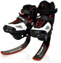
1) TRAMP-It-Jump-Shoes (in 2007 they were only abroad) :
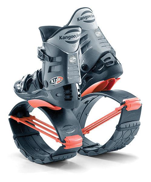
2) Kango Jumps (in 2007 they were only abroad):
3) Device Oscar Pistorius
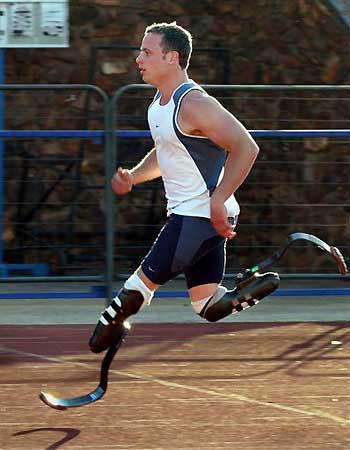
But all of these devices are not allowed to move ankle.
Later, I spent another patent search. There I found a lot more interesting things, but more on that later. I want to describe the process of how it was.
Prototype Development h4> This was my course of scientific research (KNIRS). I offered it to his supervisor and he approved, for which he thanks a lot! Since my Department of Instrumental Techniques and Technologies - and then the theme had to be relevant. But I twisted that developed the manufacturing technology of this design and, therefore, expected processing modes.
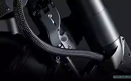
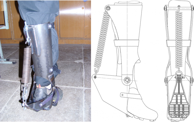
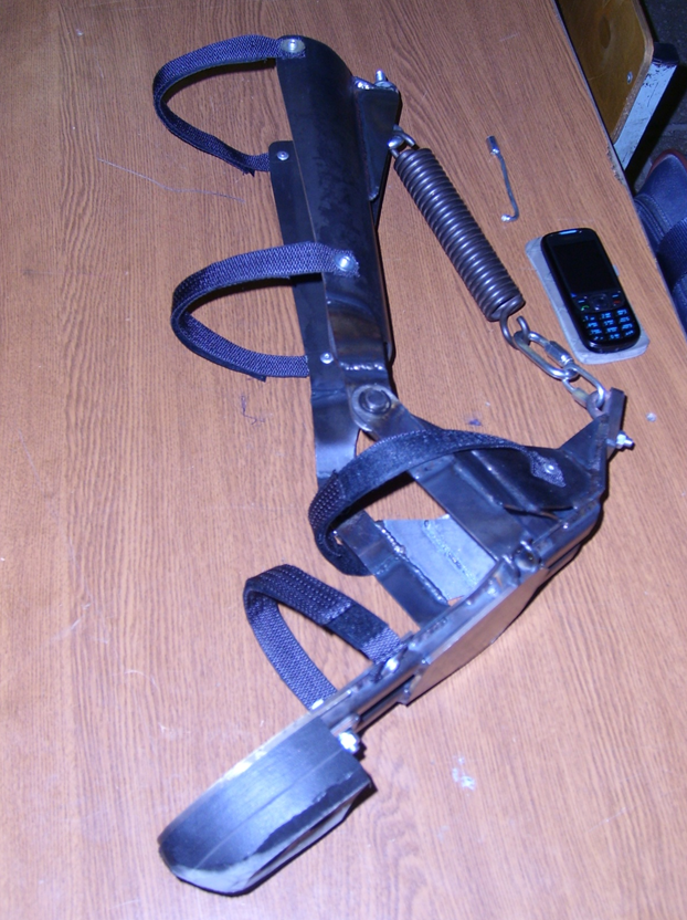
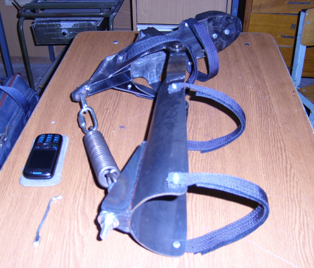
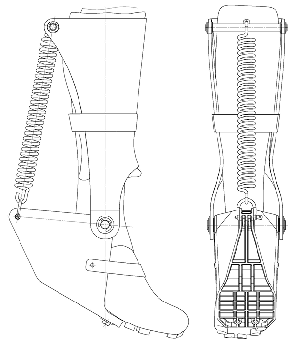
The device, which I have developed consists of the foot (red), the release of eggs (green), metatarsus (black) and spring (blue). Leg (blue) attached to the device by means of belts (gray). Between the foot and calf lock desirable to place a piece of felt to lock does not rub his leg.
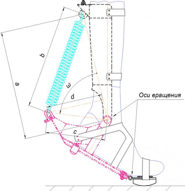
The foot can be rotated with respect to the release of eggs. The axis of rotation is shown in the figure, it is aligned with the axis of rotation of the foot relative to the lower leg (ankle).
In the unstressed state the spring is in a compressed state. Stop drawn. By pulling the foot "over the" spring is stretched and creates a force that seeks to pull the foot.
Hock (black) can rotate freely (pull over and away from you). Thus ^ can stand still and walking. However, the device can be made with a rigid, non-rotating metatarsus. Such a construction would be less comfortable walking and standing, but it can transmit more power by using more spring stroke.
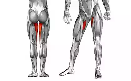
The device does not replace the power that creates muscle agonists shin, namely increases it gives strength gain to it. At the same agility movements remain almost completely.
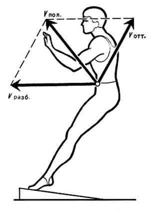
The scheme works as follows:
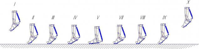
I - Moment of flight (fall). Man jumping from a height or from the previous jump.
II-III - the moment of contact. Powered sock feet. C-drawn position he moves horizontally.
III-V - Stretching spring. At this period to force the calf muscles added force from the spring. Also at this stage, the damping force of falling (depreciation). The strength of the spring takes some of the load itself. To V maximum spring is stretched.
V-VIII - compression spring. Calf muscles contract and give strength to jump. To this is added the power of the force from the spring. Hence the repulsive force increases.
VIII-IX - Finalization of the toe. At this point, there is a final dotalkivanie due pulling sock. This dotalkivanie sets the direction of flight of the foot (in conjunction with the work of his hands, the deviation of the body and work the muscles of the thigh). Also drawn socks are the result of proper operation while pushing off during a jump.
Selecting the main dimensions h4> The first step is designed appearance. That is approximately described by the kinematic scheme. Took advantage MathCad'om for calculating the optimum geometry and stiffness of the spring. That is, such a geometry that would give maximum efficiency of use.
To determine when the time was composed equation relative to the point of rotation of the foot relative to the tibia:
M = d ∙ F, where d - shoulder, F = k ∙ x - the spring force.
k - spring, x - tension springs.
Next, it was necessary to obtain the dependence of the moment M of the rotation angle ω.
Shoulder length dependence of the rotation angle:
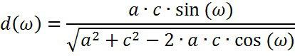
The dependence of the tensile springs from the angle of rotation:

Where H - the length of the spring in a relaxed state.
The general equation of the time, depending on the angle of rotation:

Further, since a schedule depending on the rotation angle (in radians):
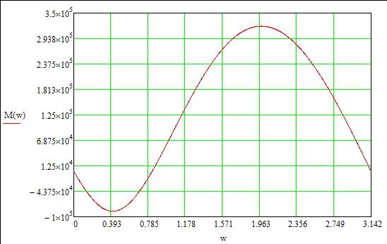
From this graph, I found that the best use of design steering angle of 60◦ to 100◦.
The prototype was designed with the help of CATIA V5 R19. Strength characteristics were calculated details thereof. Material of body parts - steel 3. The thickness of the sheet from which these items were made - 2 mm.

Since I was a poor student, the money I did not have much. Almost all operations were to be carried out by professionals. And to Uncle Vasya the first time did the right thing that I want to, you must describe the item so that it was clear and a hedgehog. I made drawings of all the parts, assembling parts with all allowances and so on. In the end, I first sheet cutting factory, which hosted the practice. Cutting sheet passes on the EDM machines (wire) Fanuc. Yeah ... I probably do not even know how to create a manufacturing process even more expensive. In any case, it came to me very cheap, as an acquaintance. Although Babin wire used new (!!!), since the machine is designed so that the exhaust wire breaks. This is done so that the wire can not be used again, and make it easier to dispose of it and blah blah blah ... Of course, this can be turned off, but then flies warranty on the machine. This machine is used for very precise operations, stood in a special heat stabilized room. Also at the factory and I vytochili tempered axis.
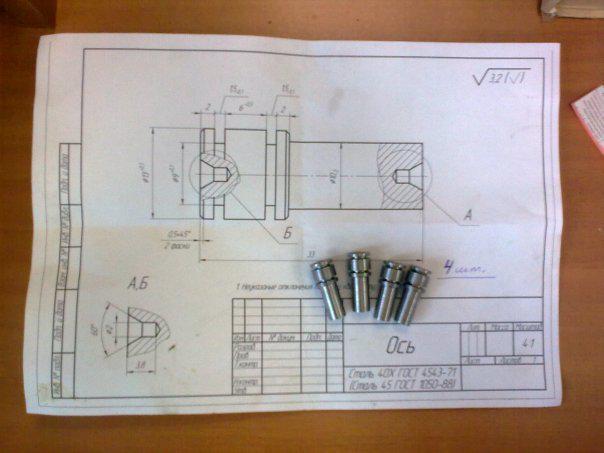
At the Institute, I was introduced to the welder. Flexible parts produced myself. The welding process took about 3 days. Countersink holes and scan, riveting straps and drill holes did myself on my chair. The diameter of the axis is chosen based on the availability of a suitable tool. That is the first I found suitable tools (drill, countersink-scan), and then create a drawing axis (see figure above). Spring I ordered on Lianozovo Research Institute Special steels. I was just surprised that the two springs on my drawings cost me only 250 rubles! And I even gave checks that actually confirms that the product conforms and drawing.
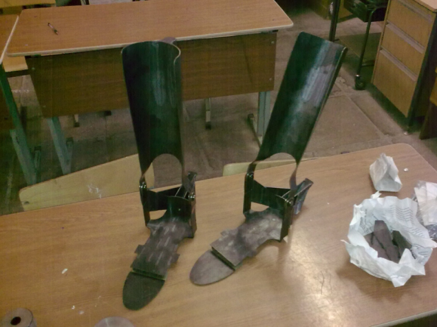
Test h4> 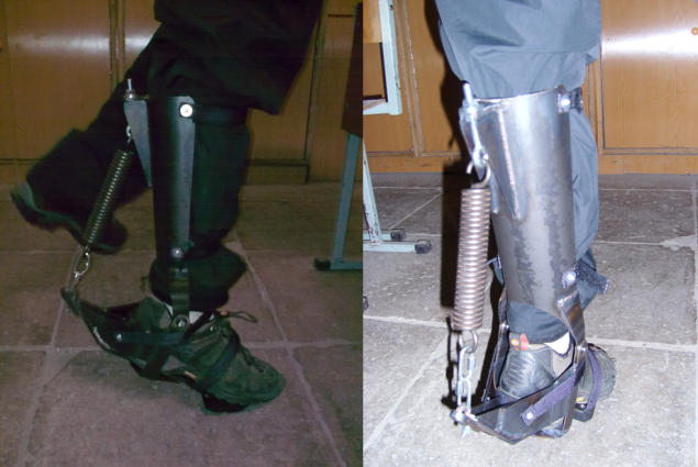
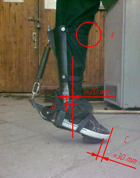
After creating the design revealed several errors:
- The spring was very hard (2000 N);
- The axis of the hinge is on (relatively heel) than the axis of the ankle joint by about 10-15 mm;
- Futpleyta length is not sufficient to stop completely stood up. Sock feet hanging from futpleyta (approximately 15 mm), which creates some discomfort;
- No ergonomic geometry of the rubber buffer sock. Need to do more rounded shape and a larger radius of curvature;
- In zone A has a concentration of effort (response) to the shin.
In general, the prototype has shown that the design functional. Weight structure (one foot) of 3 kg.
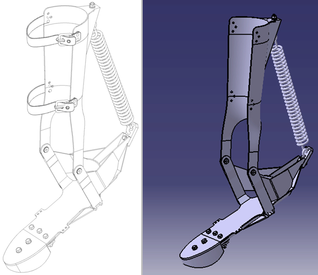
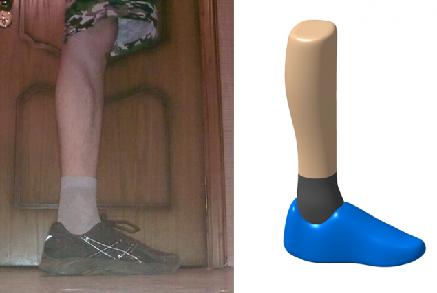
Accounting deficiencies and modeling of structures made of plastic h4> Initially modeled the human foot medium-sized and cycling track shoe company. Contact shoes have a very hard soles made of composite material. Stiff sole is a carrier force action from the nose to the spring through the footrest. For a more accurate simulation I decided to make a 3D model of your feet. I photographed a foot in two projections and created a 3D model on the basis of these projections (by the way, this approach is often used in China to quickly create 3D copies of products and the subsequent production).
It was worked out a lot of options, one of them was an option with a conventional running shoes.
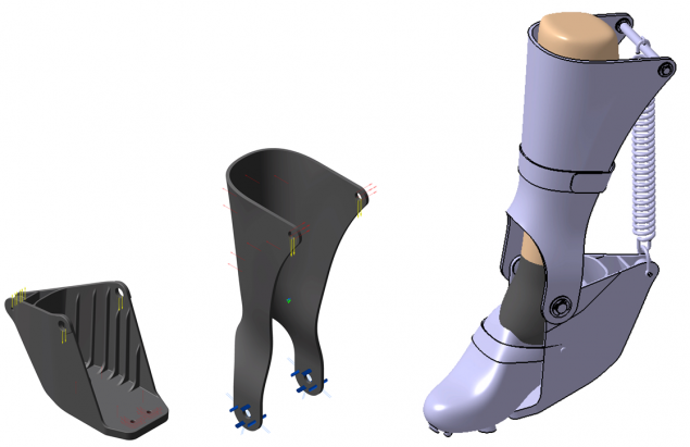
Next model shoe and feet were created two main parts: the foot lock latch and caviar. Created purely technical 3D model of the entire structure, as there was no time.
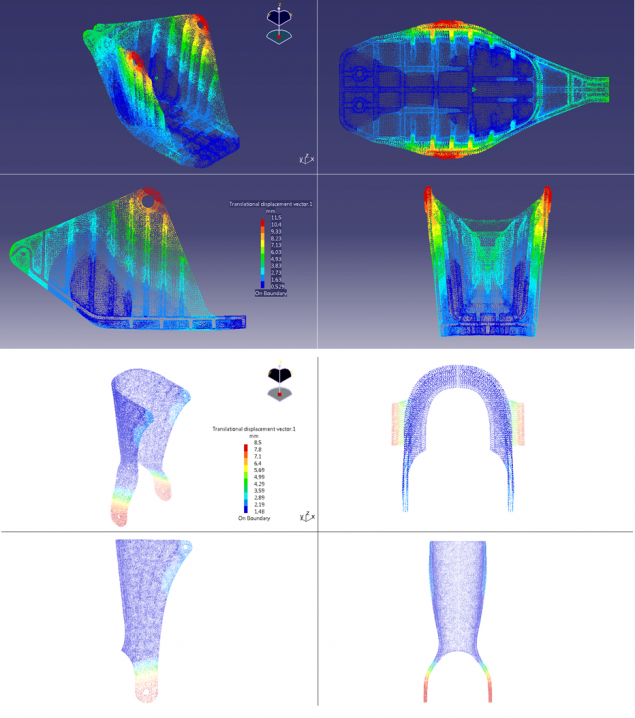
The material of construction was assigned polycarbonate PC LSV-30, since it satisfies the strength and formability characteristics and casting.
Were carried out simple calculations on the strength of the structure. The goal - to learn movement "razezzhaniya" futpleyta in the hinge locations. Calculations have shown satisfactory results. Equivalent stress on the stock also had.
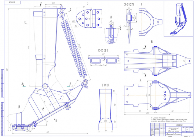
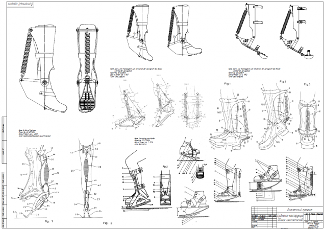
Beautiful model (with buckles and inner lining) of the general assembly then do not have time, so here are my general view drawing designs on the foot of man.
Since I was at the Department of Instrumental Techniques and Technologies, the main part of my degree was in my design technology manufacturing.
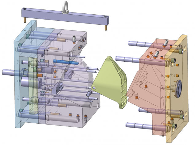
I considered several variants of forms and a variety of options: silicone created by spraying, etc. As a result, focused on the classic version. The module CATIA Moulding Design has developed a mold for making futpleyta. Form made of standard components company Hasco (as in CATIA was their library and its components was too lazy to create, and there was no time). When designing a cooling system had to use specific details (like company Fodesco) for the desired distribution of the flow of cooling / warming up liquid. To reduce the cost of production (small print run of 1000 pieces per month) signs for forming holes made with a manual patch notch. Who knew that could be added to the design elements of the mortgages to the axis, but this did not make the diploma.
By the way, my form has passed the examination of designers molds, who said that it is created correctly and technologically, that is, it can already been manufactured. At a cost of manufacturing a mold happened about 7000 euros (2010).
Next was established manufacturing process matrix. That is, the selection tool, processing modes, selection of equipment, tools, etc. I will not immediately result in operating sketches, because they do not think it will be interesting.
In conclusion h4> The result of this work showed that the structure is efficient. At that time, the money I was little, so to realize his idea into reality could not.
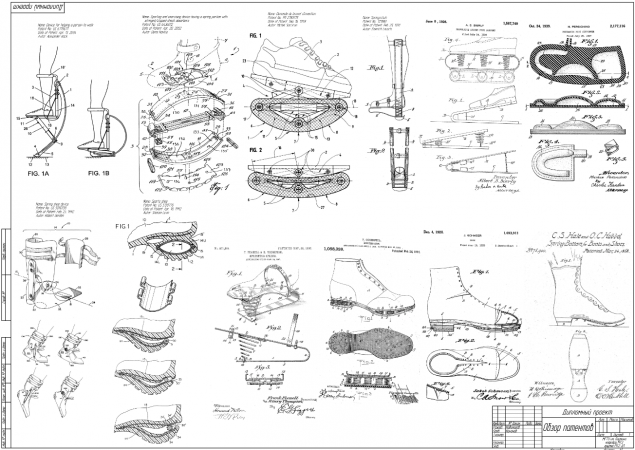
The project examined a large number of options and held a patent search, which gave interesting results, and introduced me to the German Dr. Gerd Dzhunkuntsom (Gerd Jungkunz). Then I miraculously found his e-mail on the Internet and a little chat with him about his models. It turned out that he created almost the same design and even something as experienced it (it was only available to a garage and tools grinder level, he's still a doctor of medicine). Nevertheless, further work is not gone, and he threw the case. Now the contacts I have lost, and my recent searches have been fruitless. Can anyone help? ..
Below is my selection of interesting patents on the topic:
I am currently looking into ways to be more productive elastic materials as a spring and the chance to design more ergonomic.
If anyone is interested in my work, I am ready to cooperate, as in the whole theme of exoskeletons and various human power amplifiers is interesting to me.
Source: geektimes.ru/post/242596/