542
Drainage area with your hands: WHAT you need to know
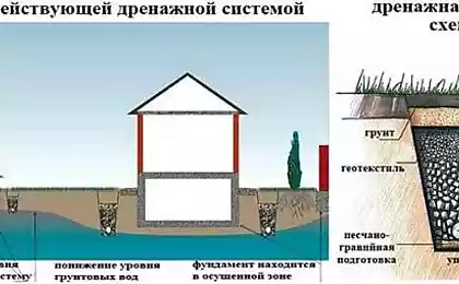
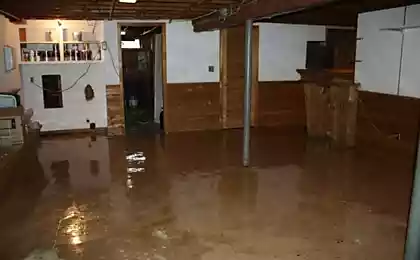
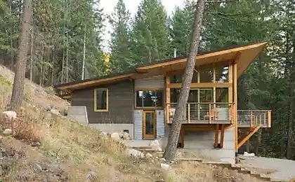
Ground water is able to clean the soil under the Foundation of a country house that can cause severe settling of the building. Also perched groundwater can seriously hinder the growing of many fruit trees. How to make a drainage area with your hands, you will learn from this article.
The necessary materials for drainageFor drainage will need the following materials:
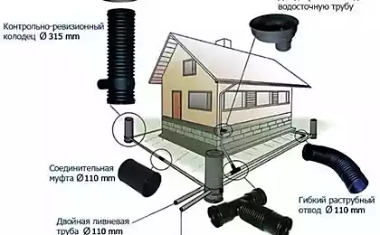
Coarse-grained dredged sand. The gravel fraction 20-40 mm Washed gravel fraction 5-20 mm Gravel fraction 40-60 mm. Geotextiles. Perforated drain pipes. Plastic drainage shafts with a shaft diameter of 300-400 mm.
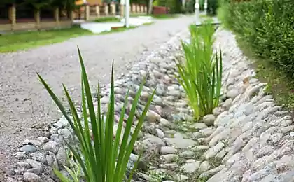
Make a draft of future drainage systemtype of drainage system is divided into open and closed. An open drain implies the presence on the surface of the soil waste trenches, which due to the small bias will be to take away excess groundwater or rainwater. Most often this technology is used in the agricultural sector in the fields or plots with a large area. We are talking about a country house with a plot of 6 acres. So for us, the best option will be a closed drainage system.
While designing the drainage system it is necessary to consider the following points:
The type of soil. The upper level flow of groundwater in the not rainy season. The total area of the plot. The level of cushion Foundation.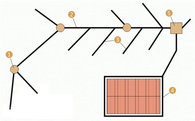
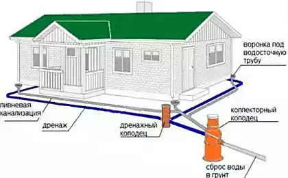
Draft drainage system: 1 — drain well; 2 — main drains, 3 for collecting drains; 4 — trench around the house; 5 — the Central shaft
The classic layout of the drains is their device parallel to each other, respecting the distance calculated from the soil type. In this case, the corners of the outermost drain install the plastic drain reservoirs, to which the interim drain. That is, it turns out cascading underground drainage system.
Drainage pipes are laid at 30-50 cm below the level of freezing. If the Foundation is below this level, the laying drains should be done on Gubin below 50 cm the Foundation.
The distance between parallel drains is calculated on the basis of the table data:
The drain depth, m Distance between the drains, m light soils medium soils heavy clay soils 1,8 18-22 15-18 7-11 1,5 15,5–18 12-15 6,5–9 1,2 12-15 10-12 4,5–7 0,9 9-11 7-9 4-5,5 0,6 6,5–7,5 5-6,5 3-4 0,45 4,5–5,5 4-5 2-3 pipe-Laying is carried out with the bias that is 2 cm by 1 meter trench. The gradient produced in the direction of the well from which water is discharged from the site.
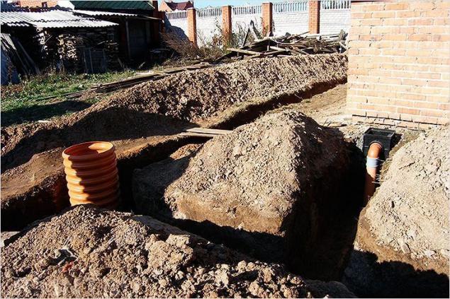
Breakdown and excavation workBreakdown is a process of transferring the location of drains and sewers with the paper plan on the ground. The future location of the main elements of the drainage system at the ground surface indicate the hammered wooden pegs with strained on them with string.
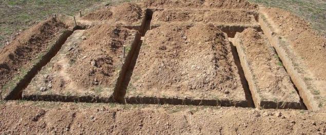
After performing breakdown begin the excavation work, i.e. trench. Profile drainage trench in most cases performed in the form of an inverted trapezoid. The width of the trench at the bottom shall be 40 cm and the top at the surface of the soil is 60-70 cm in the earthworks and digging trenches about 50% of the selected soil is removed from the plot forever. The remaining soil are placed along the created trenches for backfill.
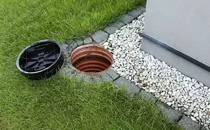
Installation of intermediate collectorsAfter sampling of the soil and the creation of all drainage ditches, the bottom is leveled to obtain the necessary slope and thoroughly compacted. Further, the locations of drainage collectors produce an additional sample of soil, a depth of approximately 30-40 cm Soil under the future collectors and rams poured sand cushion thickness of 10-15 cm After that, the bottom of the shaft the plastic manifold valuesa a special cover and you are installing on compacted sand cushion. After completion of all work, the reservoir should be cut at ground level and close with a special hatch.
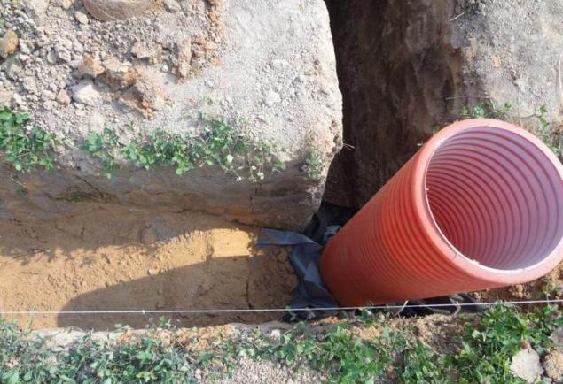
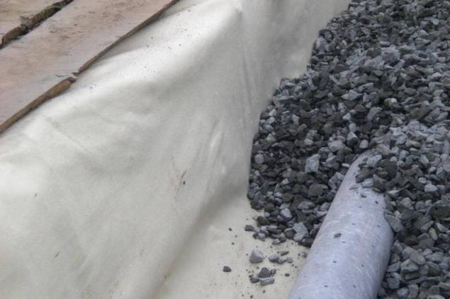
Laying of geotextiles and drainage pipesAt the bottom of trenches is filled with a bed of coarse sand with a height of about 10 cm and thoroughly compacted. Next to the sand cushion is filled with a layer of crushed stone of fraction 20-40 mm, a height of 15 cm Rethrownew gravel for the length of the trench, start laying the geotextile. The cloth is cut and fitted so that it completely covers covered with gravel the bottom of the trench and both walls of the trench to the surface of the soil.
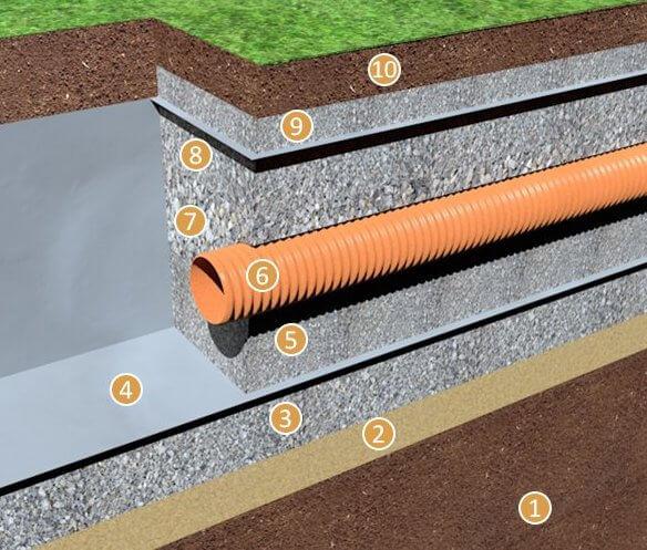
Schematic diagram of the drainage trench: 1 — soil; 2 — coarse sand; 3 — gravel fraction 20-40 mm; 4 — kerosene; 5 — gravel fraction 5-20 mm; 6 — drain; 7 — gravel of fraction 40-60 mm; 8 — gravel fraction 20-40 mm; 9 — gravel fraction 5-20 mm; 10 — backfill
After laying of geotextiles on the bottom of the trench is poured a layer of washed gravel (5-20 mm) thickness of 15-20 cm Gravel is spread on the entire length and on its base is laid perforated drainage pipes made of PVC with a diameter of 110 mm. At this stage, when it is known the height and position of drainage pipes plastic vertical collectors with crowns produce holes for connecting them to drainage pipes. As a rule, connection of drainage pipes with vertical headers is done with special couplings, having in its design the o-rings. The connection between drainage pipes perform a normal or a t-coupling PVC.
Filling filling drainage trenchesLaid drainage pipes and brought them to the collectors, thereby creating a cascading system, the edges and top of the pipe is filled with a layer of 10-15 cm coarse gravel fraction 40-60 mm. the Surface of the drainage pipe can be run over a large stone, like river stone or a small booth sizes. As the filler layer will be used for the transmission of ground water and protect the drainage pipes from deformation.
On top of the coarse gravel poured bed of gravel fraction 20-40 mm and height of 20 cm, and then the edges of the geotextile fabric overlap cover the gravel. On top of the geotextile poured a small layer of gravel in the 5-10 cm fraction 5-20 mm., then drainage trenches filled selected during excavation with soil. Taking into account the fact that the soil settles, filling produce above ground level.
Drainage of water from the drainage systemPerformed as described, a drainage system will accumulate water in the lower level of the intermediate manifold. Drainage it can be gravity fed through the inclined in the soil pipe through which water is discharged from the collector into the nearest gutter, or forcibly installed in the reservoir water submersible pump, for example, "Trickle". When the water discharge pump is necessary to provide in the circuit connecting the switch "frog". published
P. S. And remember, only by changing their consumption — together we change the world! ©
Source: www.rmnt.ru/story/landscapedesign/933503.htm

The necessary materials for drainageFor drainage will need the following materials:
Coarse-grained dredged sand. The gravel fraction 20-40 mm Washed gravel fraction 5-20 mm Gravel fraction 40-60 mm. Geotextiles. Perforated drain pipes. Plastic drainage shafts with a shaft diameter of 300-400 mm.
Make a draft of future drainage systemtype of drainage system is divided into open and closed. An open drain implies the presence on the surface of the soil waste trenches, which due to the small bias will be to take away excess groundwater or rainwater. Most often this technology is used in the agricultural sector in the fields or plots with a large area. We are talking about a country house with a plot of 6 acres. So for us, the best option will be a closed drainage system.
While designing the drainage system it is necessary to consider the following points:
The type of soil. The upper level flow of groundwater in the not rainy season. The total area of the plot. The level of cushion Foundation.

Draft drainage system: 1 — drain well; 2 — main drains, 3 for collecting drains; 4 — trench around the house; 5 — the Central shaft
The classic layout of the drains is their device parallel to each other, respecting the distance calculated from the soil type. In this case, the corners of the outermost drain install the plastic drain reservoirs, to which the interim drain. That is, it turns out cascading underground drainage system.
Drainage pipes are laid at 30-50 cm below the level of freezing. If the Foundation is below this level, the laying drains should be done on Gubin below 50 cm the Foundation.
The distance between parallel drains is calculated on the basis of the table data:
The drain depth, m Distance between the drains, m light soils medium soils heavy clay soils 1,8 18-22 15-18 7-11 1,5 15,5–18 12-15 6,5–9 1,2 12-15 10-12 4,5–7 0,9 9-11 7-9 4-5,5 0,6 6,5–7,5 5-6,5 3-4 0,45 4,5–5,5 4-5 2-3 pipe-Laying is carried out with the bias that is 2 cm by 1 meter trench. The gradient produced in the direction of the well from which water is discharged from the site.
Breakdown and excavation workBreakdown is a process of transferring the location of drains and sewers with the paper plan on the ground. The future location of the main elements of the drainage system at the ground surface indicate the hammered wooden pegs with strained on them with string.

After performing breakdown begin the excavation work, i.e. trench. Profile drainage trench in most cases performed in the form of an inverted trapezoid. The width of the trench at the bottom shall be 40 cm and the top at the surface of the soil is 60-70 cm in the earthworks and digging trenches about 50% of the selected soil is removed from the plot forever. The remaining soil are placed along the created trenches for backfill.
Installation of intermediate collectorsAfter sampling of the soil and the creation of all drainage ditches, the bottom is leveled to obtain the necessary slope and thoroughly compacted. Further, the locations of drainage collectors produce an additional sample of soil, a depth of approximately 30-40 cm Soil under the future collectors and rams poured sand cushion thickness of 10-15 cm After that, the bottom of the shaft the plastic manifold valuesa a special cover and you are installing on compacted sand cushion. After completion of all work, the reservoir should be cut at ground level and close with a special hatch.

Laying of geotextiles and drainage pipesAt the bottom of trenches is filled with a bed of coarse sand with a height of about 10 cm and thoroughly compacted. Next to the sand cushion is filled with a layer of crushed stone of fraction 20-40 mm, a height of 15 cm Rethrownew gravel for the length of the trench, start laying the geotextile. The cloth is cut and fitted so that it completely covers covered with gravel the bottom of the trench and both walls of the trench to the surface of the soil.

Schematic diagram of the drainage trench: 1 — soil; 2 — coarse sand; 3 — gravel fraction 20-40 mm; 4 — kerosene; 5 — gravel fraction 5-20 mm; 6 — drain; 7 — gravel of fraction 40-60 mm; 8 — gravel fraction 20-40 mm; 9 — gravel fraction 5-20 mm; 10 — backfill
After laying of geotextiles on the bottom of the trench is poured a layer of washed gravel (5-20 mm) thickness of 15-20 cm Gravel is spread on the entire length and on its base is laid perforated drainage pipes made of PVC with a diameter of 110 mm. At this stage, when it is known the height and position of drainage pipes plastic vertical collectors with crowns produce holes for connecting them to drainage pipes. As a rule, connection of drainage pipes with vertical headers is done with special couplings, having in its design the o-rings. The connection between drainage pipes perform a normal or a t-coupling PVC.
Filling filling drainage trenchesLaid drainage pipes and brought them to the collectors, thereby creating a cascading system, the edges and top of the pipe is filled with a layer of 10-15 cm coarse gravel fraction 40-60 mm. the Surface of the drainage pipe can be run over a large stone, like river stone or a small booth sizes. As the filler layer will be used for the transmission of ground water and protect the drainage pipes from deformation.

On top of the coarse gravel poured bed of gravel fraction 20-40 mm and height of 20 cm, and then the edges of the geotextile fabric overlap cover the gravel. On top of the geotextile poured a small layer of gravel in the 5-10 cm fraction 5-20 mm., then drainage trenches filled selected during excavation with soil. Taking into account the fact that the soil settles, filling produce above ground level.
Drainage of water from the drainage systemPerformed as described, a drainage system will accumulate water in the lower level of the intermediate manifold. Drainage it can be gravity fed through the inclined in the soil pipe through which water is discharged from the collector into the nearest gutter, or forcibly installed in the reservoir water submersible pump, for example, "Trickle". When the water discharge pump is necessary to provide in the circuit connecting the switch "frog". published
P. S. And remember, only by changing their consumption — together we change the world! ©
Source: www.rmnt.ru/story/landscapedesign/933503.htm