332
How to make push-button radio switch touch
Long dreamed of the house to install the touch switch, the dream came true when I was given a cheap touch switch FD Electronics. Looks nice, works fine. But it's just a switch, and I have the clever house on the basis of Z-Wave and of course I wanted to integrate it into their system.
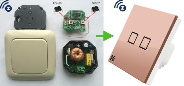
From FD Electronics, Livolo and DeLumo are radio switches operating at the frequency of 433MHz and 868MHz, respectively, but to integrate them into the smart house will not work. These switches only work with the same panels manufacturers, control no computer, no feedback, i.e. if someone switches the light on I'll never hear about it.
It was decided to cross my push-button radio switch Z-Wave.Me Dimmer touch switch FD Electronics. After studying the diagrams of both switches, I decided to throw the power part touch switch and use only the case and touch panel, and from your Z-Wave switch to get power and a radio part. The essence of the alteration is to replace the mechanical buttons on the touch, this method is suitable for the switch of any technology.
The most popular chip to create a touch button is TTP-223. The main feature of TTP-223 is the ability to autocalibrate. When power is applied the chip measures the capacitance on the stem of the sensor I and takes it as 0, it is convenient because you do not need to configure anything. When you touch the sensor on the leg Q , a voltage is applied, there is the connected load (LED, relay, optocoupler).

With the help of legs TOG and AHLB is configured in response to a touch on the sensor. I configured the power mode, connecting the TOG and AHLB with the earth, this means that when I touch the sensor on the leg Q voltage appears, when you release the sensor, the voltage disappears. Still it is possible to configure the switching mode, then each touch puts the foot Q to the opposite state.
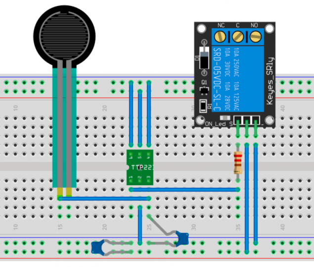
To test TTP-223 on a breadboard assembled circuit management April for Arduino. Works great.
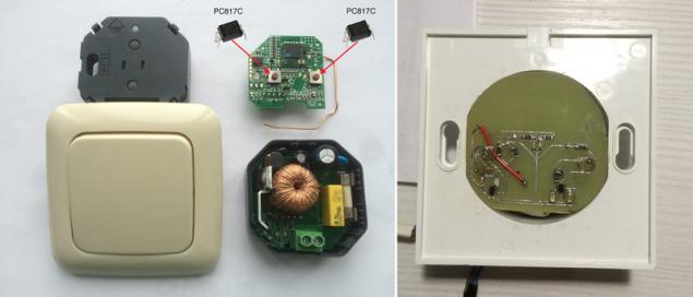
To simulate pressing physical buttons, I used the optocoupler PC817C. The coupler I soldered instead of the buttons on my dimmer. When voltage is applied to the optocoupler, it is closed, the dimmer it's like pushing the button. Using the LOOT was made charge adapter, on the one hand the scheme of the sensor, on the other optocoupler.
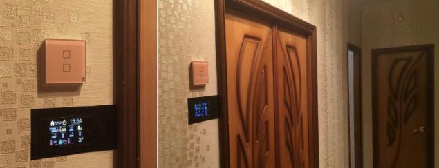
Combining all of this sandwich I got touch Z-Wave dimmer. To all the tests and the Assembly took 2 in the evening. Switch installed in the corridor, where it is controlled by the motion sensor, but if you want to force disable or enable a certain level of brightness, you can gently touch the beautiful!
PS. The experience I decided to use it to create touch switch battery-powered, and have already ordered from aliexpress touch panel switch Livolo, but more on that later.
P. S. And remember, only by changing their consumption — together we change the world! ©
Join us in Facebook , Vkontakte, Odnoklassniki
Source: geektimes.ru/company/zwave/blog/274122/

From FD Electronics, Livolo and DeLumo are radio switches operating at the frequency of 433MHz and 868MHz, respectively, but to integrate them into the smart house will not work. These switches only work with the same panels manufacturers, control no computer, no feedback, i.e. if someone switches the light on I'll never hear about it.
It was decided to cross my push-button radio switch Z-Wave.Me Dimmer touch switch FD Electronics. After studying the diagrams of both switches, I decided to throw the power part touch switch and use only the case and touch panel, and from your Z-Wave switch to get power and a radio part. The essence of the alteration is to replace the mechanical buttons on the touch, this method is suitable for the switch of any technology.
The most popular chip to create a touch button is TTP-223. The main feature of TTP-223 is the ability to autocalibrate. When power is applied the chip measures the capacitance on the stem of the sensor I and takes it as 0, it is convenient because you do not need to configure anything. When you touch the sensor on the leg Q , a voltage is applied, there is the connected load (LED, relay, optocoupler).

With the help of legs TOG and AHLB is configured in response to a touch on the sensor. I configured the power mode, connecting the TOG and AHLB with the earth, this means that when I touch the sensor on the leg Q voltage appears, when you release the sensor, the voltage disappears. Still it is possible to configure the switching mode, then each touch puts the foot Q to the opposite state.
To test TTP-223 on a breadboard assembled circuit management April for Arduino. Works great.

To simulate pressing physical buttons, I used the optocoupler PC817C. The coupler I soldered instead of the buttons on my dimmer. When voltage is applied to the optocoupler, it is closed, the dimmer it's like pushing the button. Using the LOOT was made charge adapter, on the one hand the scheme of the sensor, on the other optocoupler.

Combining all of this sandwich I got touch Z-Wave dimmer. To all the tests and the Assembly took 2 in the evening. Switch installed in the corridor, where it is controlled by the motion sensor, but if you want to force disable or enable a certain level of brightness, you can gently touch the beautiful!

PS. The experience I decided to use it to create touch switch battery-powered, and have already ordered from aliexpress touch panel switch Livolo, but more on that later.
P. S. And remember, only by changing their consumption — together we change the world! ©
Join us in Facebook , Vkontakte, Odnoklassniki
Source: geektimes.ru/company/zwave/blog/274122/

