1180
History of the creation of another robot. Part Two, «it's alive!»
Continues the series about creating a simple wheeled robot microcontroller ATmega16A.
In second i> of my post, I'll describe how to create and build their robot. Let's start with the manufacture of printed circuit board and finish as the first steps (correct to say - scroll wheel) of our device. Also be given to the first experience of programming under PC to Qt, namely the creation of a program management and data exchange with the robot via Bluetooth.
If you want, you can read the first publication and learn how it all started, well, everyone else asking a cat.
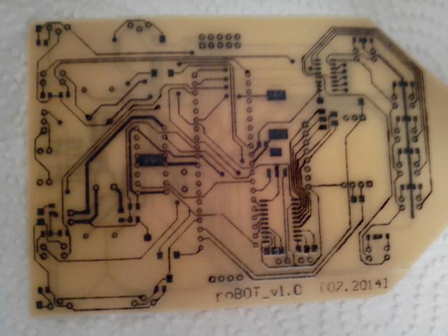
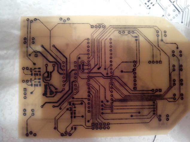
The last part ended on that in front of us wore a finished PCB layout, and then it's time to create and transfer our idea of the electronic version of the real tangible world, is not a desire to burn in the mind of each radio amateur, engineer, inventor ?! In my arms was only 1mm PCB, so I'm not thinking began the process of transferring to the drawing board tracks standard loot.
I apologize for the quality of the photos, but I have a cheap phone ...
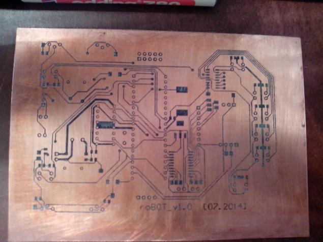
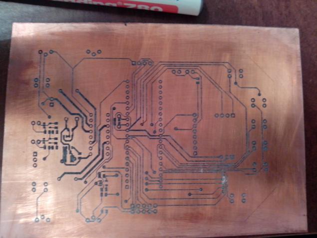
The next step was to etch! Tried a new way of etching using hydrogen peroxide and citric acid, the method of course safe and very cheap, but seemed too sensitive to the proportions of the components. After an hour of magical manipulation of containers with the solution process started with decent power (it should be said that it was possible to change the pattern board and then it would all corrode much faster).
80-90% of the tracks on the board to get a good, but because basically tracks were 0.2mm, caught a mordant, which I removed with solder and thin wires, because of them did the same vias. In general, the whole process took a soldering 3pm.
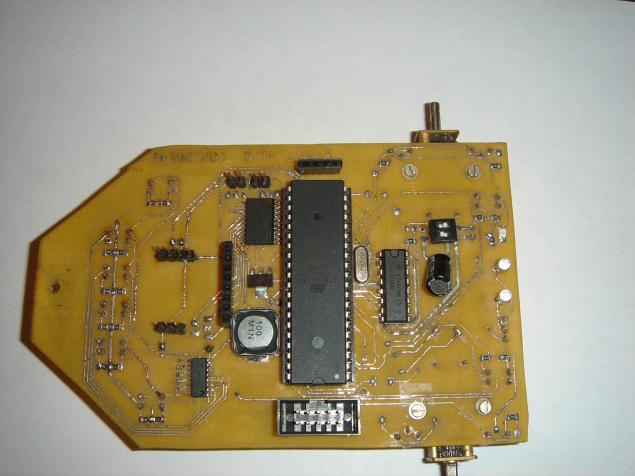
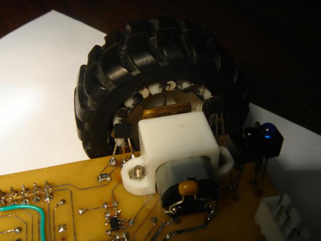
The engines had to be moved to the bottom of the board, as I realized that I needed the maximum gap between the board and the surface on which you want to go, but still the robot turned to the low-slung.
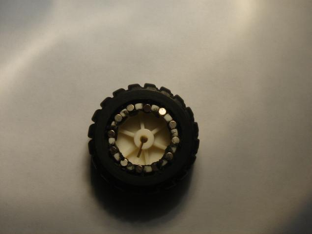
And once we remembered the motors, the recall and the idea with the encoder, as the magnets that I ordered were in diameter literally on the floor of a millimeter smaller than the slots in the wheel, they had to somehow fix it, and we know The concept is simple - I just picked up and drove them back to the bay at the same time of the glue gun is not very aesthetically pleasing, but quick and practical. The main thing is not to reverse the polarity, and it will be up to the jambs, and she so small - 12 magnets on the wheel, that is, 6 activation in turn, and with a diameter of 43mm wheels get about 22mm wheel path traversed in a single operation.
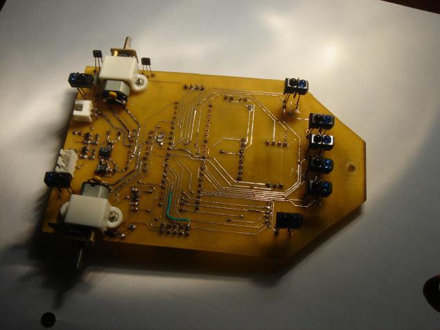
The board, in turn, with a small spacing adjustment put Hall sensors that would understand in what direction moving.
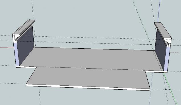
For fixing the battery, servos and ultrasonic range finder has been printed on a 3D printer is just details.
Battery holder.
Holder serfs.
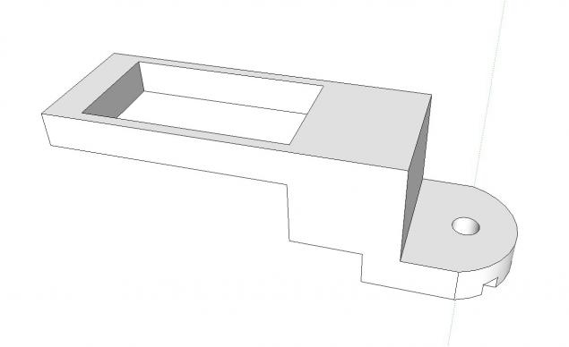
The holder of the ultrasonic range finder.
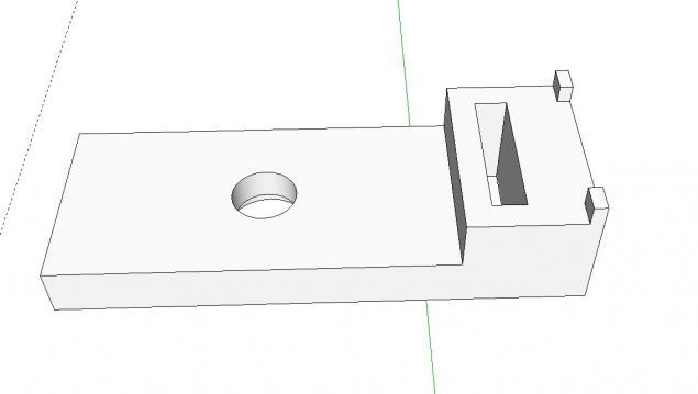
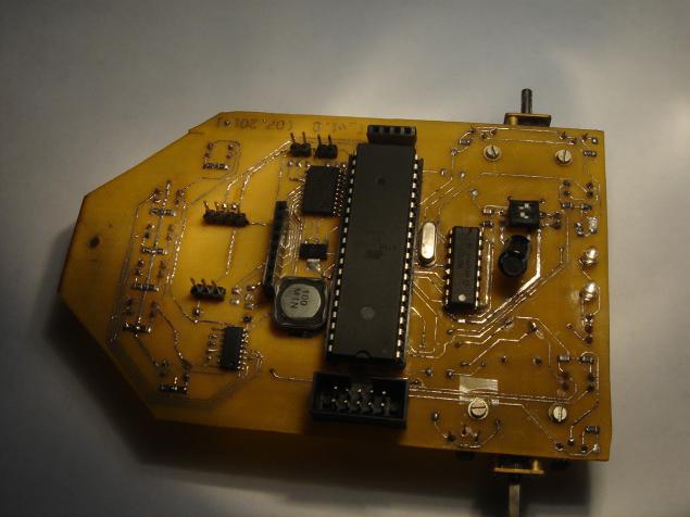
A little fine-tuning the details file and everything fell into place, in the end turned out like this robot.
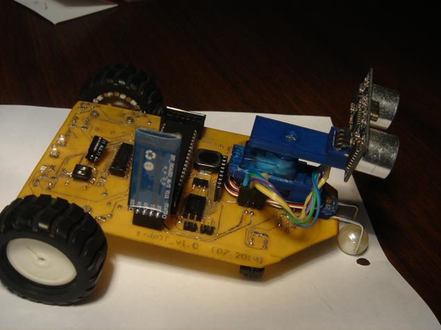
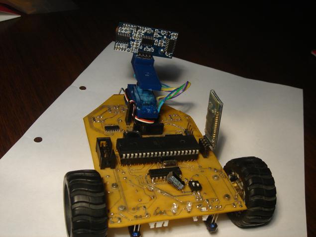
And yes, it's just a bead, bead on a thick wire, and it is so far the only unresolved "problem" design. In fact, did not take up the question of the third wheel on fire for podrygat wheels twirl Servais, etc.
From the use of 1mm PCB robot seems hlyupkim, but since we have a small mass that does not affect its strength and agility.
Well, first of all wanted to ride on the line, so to speak first experience with automated controls.
I must say that I am not a programmer by profession and this is probably my weakest point in the hobby, so please do not criticize much code, in any case, I am sure that we will have to rewrite the entire program in the future.
Was written a test program that implements the algorithm PD. It consisted of an interrupt handler ADC and the actual main loop work with the data.
The interrupt handler
In second i> of my post, I'll describe how to create and build their robot. Let's start with the manufacture of printed circuit board and finish as the first steps (correct to say - scroll wheel) of our device. Also be given to the first experience of programming under PC to Qt, namely the creation of a program management and data exchange with the robot via Bluetooth.
If you want, you can read the first publication and learn how it all started, well, everyone else asking a cat.

The last part ended on that in front of us wore a finished PCB layout, and then it's time to create and transfer our idea of the electronic version of the real tangible world, is not a desire to burn in the mind of each radio amateur, engineer, inventor ?! In my arms was only 1mm PCB, so I'm not thinking began the process of transferring to the drawing board tracks standard loot.
I apologize for the quality of the photos, but I have a cheap phone ...


The next step was to etch! Tried a new way of etching using hydrogen peroxide and citric acid, the method of course safe and very cheap, but seemed too sensitive to the proportions of the components. After an hour of magical manipulation of containers with the solution process started with decent power (it should be said that it was possible to change the pattern board and then it would all corrode much faster).


80-90% of the tracks on the board to get a good, but because basically tracks were 0.2mm, caught a mordant, which I removed with solder and thin wires, because of them did the same vias. In general, the whole process took a soldering 3pm.


The engines had to be moved to the bottom of the board, as I realized that I needed the maximum gap between the board and the surface on which you want to go, but still the robot turned to the low-slung.
And once we remembered the motors, the recall and the idea with the encoder, as the magnets that I ordered were in diameter literally on the floor of a millimeter smaller than the slots in the wheel, they had to somehow fix it, and we know The concept is simple - I just picked up and drove them back to the bay at the same time of the glue gun is not very aesthetically pleasing, but quick and practical. The main thing is not to reverse the polarity, and it will be up to the jambs, and she so small - 12 magnets on the wheel, that is, 6 activation in turn, and with a diameter of 43mm wheels get about 22mm wheel path traversed in a single operation.

The board, in turn, with a small spacing adjustment put Hall sensors that would understand in what direction moving.

For fixing the battery, servos and ultrasonic range finder has been printed on a 3D printer is just details.
Battery holder.

Holder serfs.

The holder of the ultrasonic range finder.

A little fine-tuning the details file and everything fell into place, in the end turned out like this robot.


And yes, it's just a bead, bead on a thick wire, and it is so far the only unresolved "problem" design. In fact, did not take up the question of the third wheel on fire for podrygat wheels twirl Servais, etc.
From the use of 1mm PCB robot seems hlyupkim, but since we have a small mass that does not affect its strength and agility.
Well, first of all wanted to ride on the line, so to speak first experience with automated controls.
I must say that I am not a programmer by profession and this is probably my weakest point in the hobby, so please do not criticize much code, in any case, I am sure that we will have to rewrite the entire program in the future.
Was written a test program that implements the algorithm PD. It consisted of an interrupt handler ADC and the actual main loop work with the data.
The interrupt handler
 & lt; code & gt; #define FIRST_ADC_INPUT 2 #define LAST_ADC_INPUT 7 unsigned int real_adc [8] = {0, 0, 0, 0, 0, 0, 0, 0}; unsigned char sample_adc; volatile unsigned char adc_ready = 0; unsigned char leds [8] = {0x21, 0x41, 0x61, 0x63, 0x23, 0x43}; unsigned char adc_inputs [8] = {0, 1, 2, 4, 6, 7, 3, 5}; interrupt [ADC_INT] void adc_isr (void) ////////////// ADC_INT {static unsigned char input_index = 0; if (adc_ready == 0) {if (sample_adc == 0) {real_adc [input_index] = (signed int) (ADCW); if (input_index & lt; LAST_ADC_INPUT-FIRST_ADC_INPUT) {input_index ++; } Else {input_index = 0; PORTB = leds [input_index]; sample_adc = 1; } ADMUX = (ADC_VREF_TYPE & amp; 0xff) + adc_inputs [(FIRST_ADC_INPUT + input_index)]; ADCSRA | = 0x40; } Else {if (adc_ready == 0) {if (ADCW & gt; real_adc [input_index]) {real_adc [input_index] = (signed int) (ADCW); } Else {real_adc [input_index] = (signed int) (real_adc [input_index]); } If (input_index & lt; (LAST_ADC_INPUT-FIRST_ADC_INPUT)) {input_index ++; PORTB = leds [input_index]; } Else {input_index = 0; adc_ready = 1; PORTB & amp; = ~ (1 & lt; & lt; 0); } ADMUX = (ADC_VREF_TYPE & amp; 0xff) + adc_inputs [(FIRST_ADC_INPUT + input_index)]; } If (adc_ready == 0) {ADCSRA | = 0x40; }}}} & Lt; / code & gt;  pre>

 Implementation of PID
& lt; code & gt; if (adc_ready == 1) {adc_l = (real_adc [1] + real_adc [2]); adc_r = (real_adc [3] + real_adc [4]); error = (adc_l-adc_r); delta_error = error - old_error; // Sum_error + = error; PID = Kp * error + Kd * delta_error + Ki * sum_error; old_error = error; if (PID & gt; 0) {pwr_l + = (signed int) PID; pwr_r - = (signed int) PID; } Else {pwr_l + = (signed int) PID; pwr_r - = (signed int) PID; } For (i = 0; i & lt; (LAST_ADC_INPUT-FIRST_ADC_INPUT) +1; i ++) {real_adc [i] = 0; } ADCSRA | = 0x40; adc_ready = 0; sample_adc = 0; } & Lt; / code & gt; pre>
As I was glad to see that the robot performs the functions assigned to it, is not so sure how steep videos with absolutely smooth and fast linefolower'ami, but for me, even this result was reaching.
Then I calmed down a bit with a part of the programming of the microcontroller and realized that in the future will need to implement a program for controlling the robot from a PC and began the study of Qt, as well as the latest software for the PC, I wrote only in the university (in Pascal), and it was some -That standard laboratory Informatics, my knowledge was near zero.
offtopic, about my grand plans robot control with your smartphone and how I gave up and scored on the idea Actually, I initially felt an urge to write a program for a mobile phone on Android, but did not want to learn Java, or rather did not want to away from C, and I've got a friend who fumbled in Qt and it could be a lot to ask. At first I tried to understand himself with Zen Qbluetooth and attempts to dock with the HC-05 with the help of my Chinese Jiayu g3, but every time I ran into a problem that did not allow the HC-05 and Jiayu friends. First sinned on Qbluetooth and the fact that he does not perceive HC-05, but on the Internet found information that people start line communication via bluetooth module HC using QBluetooth or write their library after complaining to a friend about his hard life, one one day wrote a program and still managed to communicate with the robot, but unfortunately through your tablet. As a result, justifying all those that my Chinese is not support rfcomm, I gave up and decided to write all the PC.
The program was to switch modes of the robot (the follow through, keyboard control, offline) and issue (set) data from all sensors of interest (servos, sensors, line, ultrasonic range finder, motors, encoders).
After a couple of weeks, wrote the first version of the control panel control the robot. Very pleased to work with GUI in Qt - convenient.
Program code'd rather not embed, so I was not banned for the mockery of Cu. In short I would say that the program simply to signal the availability of data in QSerialPort takes them and shove on the labels and widgets, in response to a timer, if necessary, sends a predetermined data such as position and velocity servo motors. Green field in the program is in dreams - the future map of location front of the robot.
The program accepts all available data and temporarily acts as a debugger. Has not yet implemented the keyboard control, and off-line is very crude and just seeing the robot until the obstacle is set at a predetermined angle and trying to go in a new direction. In general, as I said, the whole project until the dampness in the software part.
In the future it would be desirable to implement ambitious plans that are a little stopper understanding that it is necessary to alter the program at both the MC and the PC completely, as I made a big mistake and began to write both programs as swollen layer cake where one test module is adjacent to another, rather than as a strict structured system. But the main thing is not to give up and work on until what you have in mind in his head will not be realized in the material world because this is the meaning of a hobby.
PS In the future, I will try to write another part of the publication, so to speak as we move into the software part.
Source: habrahabr.ru/post/256209/


Legs, wings ... the main thing - the tail! The human body from the point of view Intel RealSense
Cemeteries cars