1797
The possibility of increasing energy recovery motor with mechanical brake his shaft
The article discusses the possibility of increasing the energy consumption in mechanical braking of the motor shaft. The experimental results show that energy efficiency in new construction designed with a rotating motor stator with mechanical braking, 2.5 times more than in the same motor stator with static.
known that when braking the motor can generate electricity. Such inhibition is widely used in electric vehicles, trams, trolleybuses, trains, trains, as well as in centrifuges and handling equipment (cranes, lifts, elevators), etc., but the amount of electricity generated in the modes of the mechanical brake is relatively small .
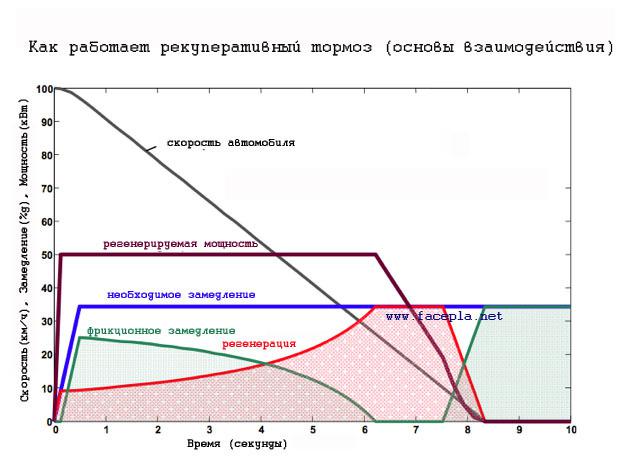
Diagrams describing one of the modes of received energy recovery in conjunction with a mechanical (friction) brake for hybrid. Graph taken отсюда.
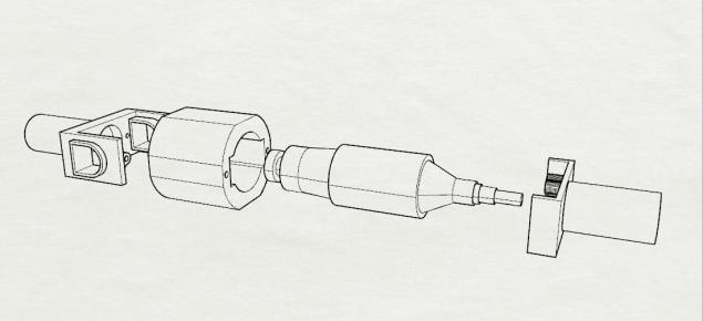
It was noted that the motor stator can rotate when braking, if allowed to do it possible, for example to put the bearing. Had the idea to use the energy of the rotating stator, ie stay here because of the mechanical brake rotor, will serve as the stator and the rotating stator, the rotor part. Schematic of this process is shown in the video, first rotor rotates conditional, with the load on the shaft, then the conditional stator:
Naturally, to achieve the desired torque on a shaft and its stator to be static. The rotational speed of the stator by mechanical braking, will depend on the progress of shaft torque, moment of inertia of the stator and the friction torque, which determines the rotation of the stator. Ie formula which describes the rotation of the stator should look like this:

- Angular (rotational) acceleration of the stator
- Angular (rotational) acceleration of the shaft before braking
- Moment of inertia of the stator
- Moment of inertia of the shaft

- Friction torque acting on the rotation of the stator
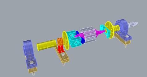
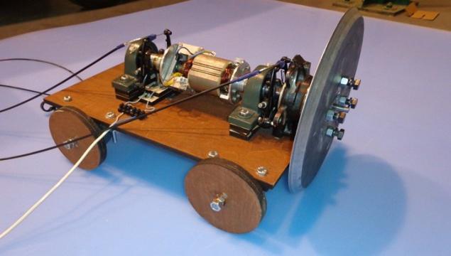
We describe the experimental details. Was an experimental setup:
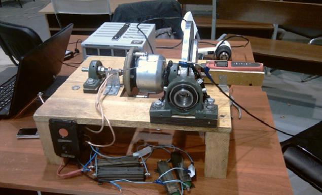
It consisted of a portable platform, which was fortified motor, brake and measuring devices. For a motor with permanent magnet excitation, 250 W, was taken from the PCB adapter, which is screwed into a steel stud, studs inserted in the housing bearing adapter allows you to rotate the stator to the bearing when braking the motor shaft, as well as by choice, for comparison, post a static stator via insertion stop.
To the motor shaft joined aluminum disk of 300 mm diameter, 10 mm thick and the disk, in turn, sets the manual mechanical brake.
When the mechanical braking energy recovery was applied in two-channel USB-oscilloscope PCS 250 oscilloscope gave the value of this energy on the computer.
To measure the energy of the setting of the second channel oscilloscope connected some 1-ohm resistors, a power of 20 W and 100 connected in parallel with each other, which serve to calculate the current in the circuit.
Data recording energy recovery with mechanical brake shaft, conducted in two modes, with no rotating stator and rotating stator. For these two modes has been selected the same maximum amount of disk rotation frequency, at which the record data from an experiment conducted, the range is from 500 to 600 rev / min. Total of 12 measurements were made for each mode.
As a result, for the treatment were taken on 8 measurements for each mode. To the arithmetic mean of maximum shaft speed before braking for the two modes were similar.
With the calculation of the standard deviation (for each mode separately) were screened results obtained energy recovery, not falling within the confidence interval.
For rotating stator arithmetic mean was 558.5 (r / min), for the static stator 559.1 (r / min).
The average of the received energy recovery with mechanical braking to the rotating stator was 5.3 J for static stator 2.04 J.
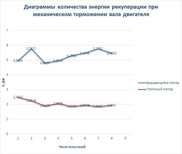
The number of tests and the number of received energy for two modes i>
Should pay attention to the polarity of the character issued by the energy recovery during mechanical braking, the electric motor in the new design of the voltage changes its polarity, the reverse:
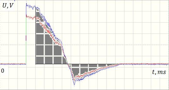
A design with static stator voltage does not change its polarity:
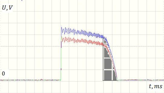
Figures shaded area of the mechanical braking. One cell on the waveform for t (time) is 200 ms for U (voltage) is equal to 0.2 in. I>
To use the energy of the reverse polarity can be used for these purposes polarity switch.
Also note that the recovery of the rotary stator mode without mechanical brake is smaller, so "on" time of rotation of the stator before the mechanical brake should be as small as possible but sufficient to the rotational energy of the rotor has moved to the stator. Judging from the oscillograms sufficient time was about 100 ms, and in this period of time not seen significant losses, you can probably still time to reduce the mechanical brake. Had the idea of making a second static stator over the rotating stator to reduce losses at no mechanical braking, but this would complicate the design of the motor.
Prior to this development was the construction of an electric motor with series excitation, in which the stator is also carried out rotation with mechanical brake shaft.
Conclusion: In the experimental design of the motor with mechanical brake shaft with rotating stator turns in 2, 5 times more than the energy recovery from static stator that illustrates the possibility to increase the energy efficiency of electric motors in the modes of mechanical braking. The amount of energy recovery here will be more than more before braking torque of the shaft and the lower the friction torque from the rotating stator and the stator for rotation allowable moment of inertia, and the smaller the shaft torque and the friction torque of the rotating more stator, etc. so the energy recovery is smaller; despite the resulting effect is worth asking about payback and reliability of design changes to the device, wherein the electric motor can be used with such effect.
Project management: Julian Baryshnikov (designing, assembling, conducting the experiment, the production of parts, article writing, idea) - iulianbaryshnikov@yandex.ru
Donate: Vitaly Azarov (designing, assembling, conducting the experiment), Sergei Langinen (designing, assembling, conducting the experiment), Anton Aleshkin (designing, assembling, manufacturing of parts), MV Yakovitsky (revised article), Alexander Troitsky (the experiment), Nikolai Eremin (meter), Alan Chumak (designing) Fablab Polytech St. Petersburg (production of parts, meter, conducting the experiment).
Source: habrahabr.ru/post/225415/

known that when braking the motor can generate electricity. Such inhibition is widely used in electric vehicles, trams, trolleybuses, trains, trains, as well as in centrifuges and handling equipment (cranes, lifts, elevators), etc., but the amount of electricity generated in the modes of the mechanical brake is relatively small .

Diagrams describing one of the modes of received energy recovery in conjunction with a mechanical (friction) brake for hybrid. Graph taken отсюда.
It was noted that the motor stator can rotate when braking, if allowed to do it possible, for example to put the bearing. Had the idea to use the energy of the rotating stator, ie stay here because of the mechanical brake rotor, will serve as the stator and the rotating stator, the rotor part. Schematic of this process is shown in the video, first rotor rotates conditional, with the load on the shaft, then the conditional stator:
Naturally, to achieve the desired torque on a shaft and its stator to be static. The rotational speed of the stator by mechanical braking, will depend on the progress of shaft torque, moment of inertia of the stator and the friction torque, which determines the rotation of the stator. Ie formula which describes the rotation of the stator should look like this:

- Angular (rotational) acceleration of the stator
- Angular (rotational) acceleration of the shaft before braking
- Moment of inertia of the stator
- Moment of inertia of the shaft

- Friction torque acting on the rotation of the stator
We describe the experimental details. Was an experimental setup:

It consisted of a portable platform, which was fortified motor, brake and measuring devices. For a motor with permanent magnet excitation, 250 W, was taken from the PCB adapter, which is screwed into a steel stud, studs inserted in the housing bearing adapter allows you to rotate the stator to the bearing when braking the motor shaft, as well as by choice, for comparison, post a static stator via insertion stop.
To the motor shaft joined aluminum disk of 300 mm diameter, 10 mm thick and the disk, in turn, sets the manual mechanical brake.
When the mechanical braking energy recovery was applied in two-channel USB-oscilloscope PCS 250 oscilloscope gave the value of this energy on the computer.
To measure the energy of the setting of the second channel oscilloscope connected some 1-ohm resistors, a power of 20 W and 100 connected in parallel with each other, which serve to calculate the current in the circuit.
Data recording energy recovery with mechanical brake shaft, conducted in two modes, with no rotating stator and rotating stator. For these two modes has been selected the same maximum amount of disk rotation frequency, at which the record data from an experiment conducted, the range is from 500 to 600 rev / min. Total of 12 measurements were made for each mode.
As a result, for the treatment were taken on 8 measurements for each mode. To the arithmetic mean of maximum shaft speed before braking for the two modes were similar.
With the calculation of the standard deviation (for each mode separately) were screened results obtained energy recovery, not falling within the confidence interval.
For rotating stator arithmetic mean was 558.5 (r / min), for the static stator 559.1 (r / min).
The average of the received energy recovery with mechanical braking to the rotating stator was 5.3 J for static stator 2.04 J.

The number of tests and the number of received energy for two modes i>
Should pay attention to the polarity of the character issued by the energy recovery during mechanical braking, the electric motor in the new design of the voltage changes its polarity, the reverse:

A design with static stator voltage does not change its polarity:

Figures shaded area of the mechanical braking. One cell on the waveform for t (time) is 200 ms for U (voltage) is equal to 0.2 in. I>
To use the energy of the reverse polarity can be used for these purposes polarity switch.
Also note that the recovery of the rotary stator mode without mechanical brake is smaller, so "on" time of rotation of the stator before the mechanical brake should be as small as possible but sufficient to the rotational energy of the rotor has moved to the stator. Judging from the oscillograms sufficient time was about 100 ms, and in this period of time not seen significant losses, you can probably still time to reduce the mechanical brake. Had the idea of making a second static stator over the rotating stator to reduce losses at no mechanical braking, but this would complicate the design of the motor.
Prior to this development was the construction of an electric motor with series excitation, in which the stator is also carried out rotation with mechanical brake shaft.


Conclusion: In the experimental design of the motor with mechanical brake shaft with rotating stator turns in 2, 5 times more than the energy recovery from static stator that illustrates the possibility to increase the energy efficiency of electric motors in the modes of mechanical braking. The amount of energy recovery here will be more than more before braking torque of the shaft and the lower the friction torque from the rotating stator and the stator for rotation allowable moment of inertia, and the smaller the shaft torque and the friction torque of the rotating more stator, etc. so the energy recovery is smaller; despite the resulting effect is worth asking about payback and reliability of design changes to the device, wherein the electric motor can be used with such effect.
Project management: Julian Baryshnikov (designing, assembling, conducting the experiment, the production of parts, article writing, idea) - iulianbaryshnikov@yandex.ru
Donate: Vitaly Azarov (designing, assembling, conducting the experiment), Sergei Langinen (designing, assembling, conducting the experiment), Anton Aleshkin (designing, assembling, manufacturing of parts), MV Yakovitsky (revised article), Alexander Troitsky (the experiment), Nikolai Eremin (meter), Alan Chumak (designing) Fablab Polytech St. Petersburg (production of parts, meter, conducting the experiment).
Source: habrahabr.ru/post/225415/


