705
How to make a swing gate operator with his own hands
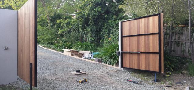
Owners sliding gates have little difficulty with self-completion of the sash drive mechanism, but if we are talking about swing gate, the effort and knowledge it takes a lot more. Today we will talk about actuators for swing gates and their Assembly with their hands.
There are three main types of gear transmission, which turns the rotation of the electric motor to linear motion with high moment of force. Mechanism design can be performed: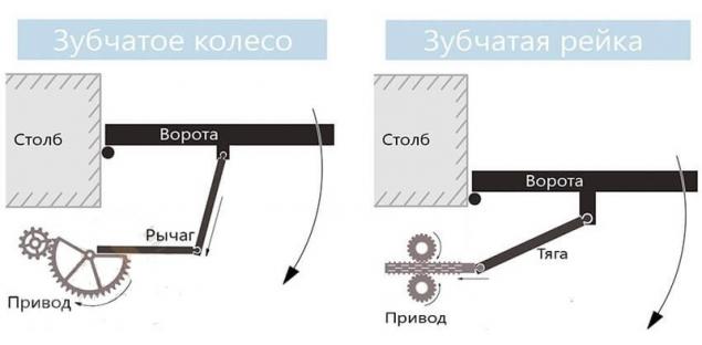
These three types of kinematics is quite possible to build your own mechanism, even at home.
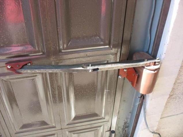
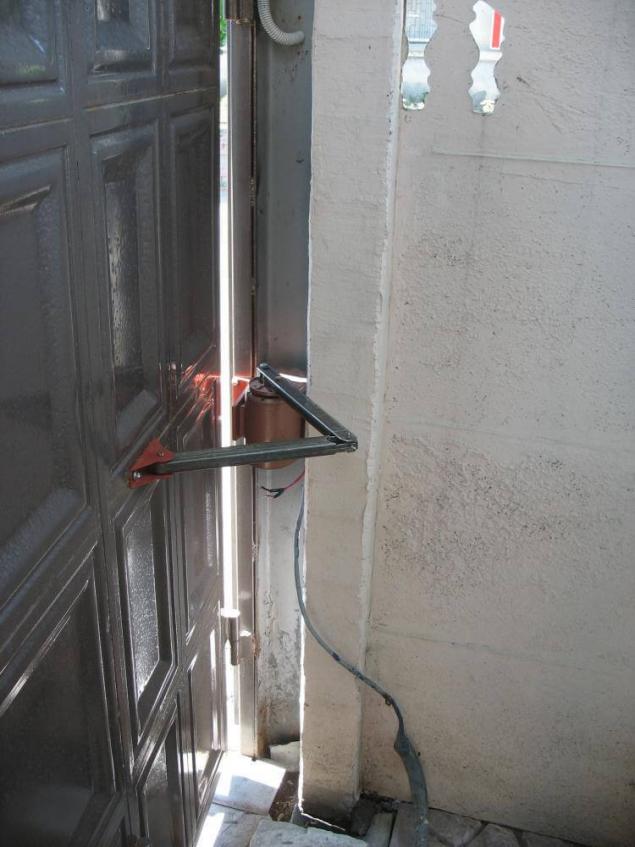
The following design improvised actuator is not afraid of moisture and dirt, he has a very high stress during movement.
Please note that at the closed gate such home-made actuator acts as a lock and cannot be opened from the outside by pressing on the shutter door.
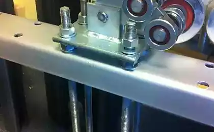
Preparation of gate and fixingComplement almost any drive can be swing gates or doors, but it is better to schedule the installation of the mechanics in advance. It concerns the installation of a reliable anchorage for the drive. They have the form of metal plates with holes at the ends, one of which is fastened perpendicularly to the leaf, the other is on a pole or fence in the same position.
When installed, the plates must be oriented in a horizontal plane and to be at the same level. It is very important to take into account the high traction drive, so the best method of fixing plate to the gate — welding. To stone and brick pillars to the plate to secure metal anchors, but much better to make items of steel in the construction phase.
The easiest way to mount the actuator on the gate that opened into the inner side, so that all actuators were located in a protected area. In the door opening must be the cable, so in advance to lay a plastic pipe of 32 mm under the road surface.
At the stage of installation of the fixtures you define the first basic parameters of your drive. Measure the distance between the centers of the holes in the fasteners when the gate is closed and when open. The latter — the length of your actuator in the folded position, and the difference between the measured distance — value of the working stroke of the device.
You can also measure the effort of opening and closing the gate using a manual spring scale. Pull the mount the gate leaf in the direction opposite to the fastener, it will help to choose the engine power.
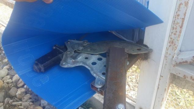
Manufacturer of automotive drive windowLight doors of the gate really set in motion the drive mechanisms of the modified Windows. The advantage of this method is its relative simplicity and nearly noiseless operation. The disadvantage is the limited tractive effort, due to the small stroke of the mechanism.
There are two types of window construction suitable for use as a drive gate:
In both cases, the drive part are mounted on a metal platform, with rigid attachment to a pole or fence. The metal rail should move parallel to the plane of the gate and ran in their direction.
The lift mechanism should be improved: installation for elongated metal traction strips or a knee lever for the gears. Connection of thrust with the drive and gates, as well as two parts of a knee lever should be in the form of a fork joint, for example a door closer.
You can provide good mobility and the absence of backlash, if one side of the joint run in the form of two stacked plates, the gap between which is equal to their thickness. This gap comprises the second plate of the hinge. Both elements are connected by a finger or a bolt with a nylock nut.
The main difficulty in the application window to find the most favorable position of the hinge and the attachment of the thrust to the gate. Surely this can be done experimentally, putting the first gate in the open position and slowly closing them, to monitor the behavior driven design. Don't forget that after the installation of the mechanism requires a protective casing.
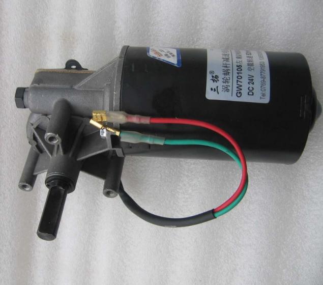
The selection and sizing of motorsas an activator of the movement for swing gates it is advisable to use motor-reducers of different types. If we are talking about a small gate small mass, cope with the problem motors rechargeable drills, drives car windscreen wipers, window regulators, etc. Another question is how you plan to use the clutch for the shafts of such engines.
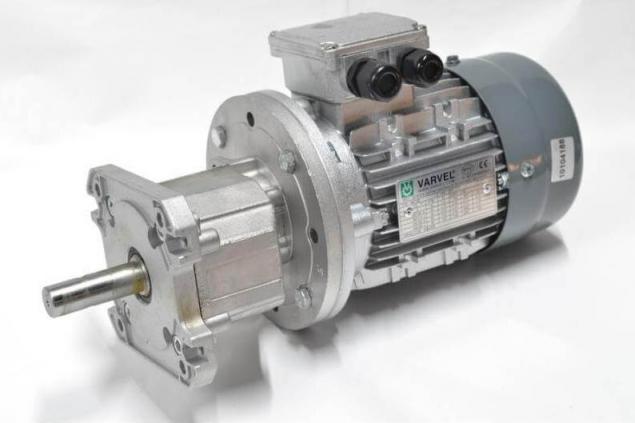
You can also choose the right units from a broad range of store geared motors, this provides greater freedom in determining the desired torque. So, let's say the measured force closing heavy doors of the gate amounted to 13.5 kg scale manual Cantera. Each kilogram corresponds to 9.8 N, so the thrust is equal 132,3 N. In the case of a rack and pinion or gear, this value must be divided by the diameter of the drive wheel, that will be equal to engine torque.
In design the type of "nut-screw" is the reduction, therefore, requires additional conversion. For example, the selected pin M18 with thread pitch of 2.5 mm. This means that for one revolution on a circle with a diameter of 18 mm 2,5 mm nut makes a translational motion, therefore the gear ratio of 7,2:1. Accordingly, if we divide the effort of opening the gate on the transmission coefficient, will receive the desired force value on the motor shaft: 132,3 / 7,2 ~ 18,4 N or slightly less than 1.9 kilograms at a radius of 0.9 cm stud That is the table value of torque for the engine will be of 1.69 kg/cm.
This is a fairly rough calculation, not taking into account the frictional force in the screw transmission and other losses, but it helps determine the minimum capacity of the motor. To compensate for energy losses it is recommended to build up a reserve capacity in the amount of 100-250%.
It is also necessary to calculate the speed of rotation of the shaft. To do this, divide the length of the stroke of the thread pitch of a helical gear, and you will receive the number of revolutions required to fully open the gate. When using rack and pinion calculation is determined by the ratio of the number of teeth on the rack and drive gear.
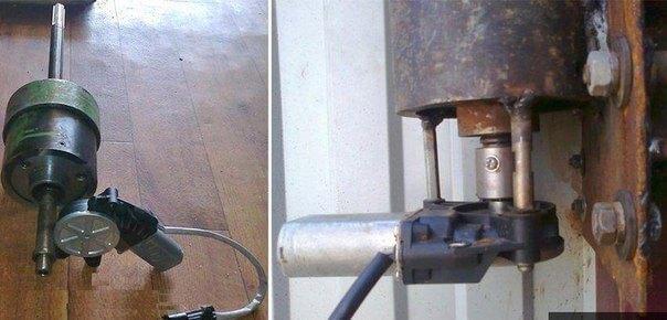
Hairpin for a homemade driveHeavy gates need to be driven with high applied force. This work fabricated the actuators, but you will be able to create an analogue of his hands.
The main difficulty is to find a suitable stud. Standard studs for the actuator are not suitable: they are made of soft metal, so over time the thread wears out. The way out is to increase the hardness of the metal and the number of contiguous threads of the screw gear.
Increase the hardness of the studs, the First task is solved by school. The right temperature heat to conventional charcoal, it is also partly inaugurative metal. Fold the horn of brick and iron railings, rascality fuel to complete burning coals. The quenching temperature is 700-800 °C, which corresponds to the deep red colour of the metal. Aging at this temperature is about 13-15 minutes, after which the detail necessary to cool the waste oil. The stud must immerse fully and simultaneously over the entire length, therefore, will dissolve the steel pipe longitudinal seam, plug the ends and use this tray as the quenching medium. The pin should be lightly shaken in oil all the time cool, then get it again and lay on the coals without wiping to release the metal. Now the heat need to run up to 200-250 degrees, while the metal does not become gray with a pronounced scale formation. After 3-4 minutes of exposure the product should be cooled in water.
The increase of the turns of thread on the studsFor the manufacture of special nuts should be screwed on the stud 2-3 standard nut flush, but not tightening. Align the faces of the nuts and clamp the Assembly in the vise is very durable. Cook the nuts in all the edges and grind the product using the LBM to its original size.
Instead of the complicated procedure of hardening you can spend time finding rolling pins and nuts for them. This metal has all the necessary features. In addition, you can choose a thread with a trapezoidal profile: it is much stronger. You can also find a product with a larger thread pitch, which will reduce the time of operation of the mechanism.
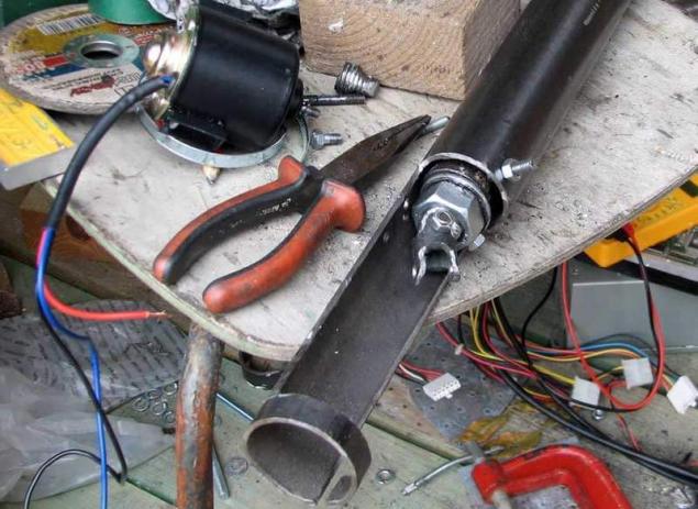
Assembly of actuatorsizing the actuatorthe Actuator has a telescopic device for its production you will need two steel pipes, one of which without a strong backlash is included in another. You can use the square tube or a round profile, not much difference. Inside both pipes should be free of rust and scale, so it is best to purchase new.
As for the size of pipes and studs, you have to calculate yourself based on the performed measurements. For example, in the folded state the length of the drive was 110 cm and the stroke is 50 cm Hence, the length of the outer tube is not more than 100 cm, it is attached a smaller tube length of 80 cm, and the length of the studs will be 110 cm or more, depending on the method of motor mounting. While in the expanded state of the actuator pipe will have an overlap of 30 cm.
The Assembly of the sliding partspass through a smaller pipe pin with a wound on her nut and position its center on the longitudinal axis of the pipe. To confidently locate the pin, do not select a too large pipe diameter. For example, if you use nut M18 with the size of the key 27 mm select a pipe with a nominal diameter of 25 mm. You will only need to uniformly grind the nut so it fits snugly into the pipe. Complete the fastening by welding. The inside of the weld is optional, but you can do it, cut out in the pipe window. When the nut is fixed, Unscrew it from the stud.
At the end of the studs need to be fixed the radial-axial bearing is closed on both sides of the separator. The outside diameter of the bearing should be approximately equal to the inner diameter of the pipe. The bearing should slide inside the tube without significant resistance, the gap between him and the wall must not exceed 1 mm. If the bearing is too tight, carefully apply on the outer end of the cage with sandpaper. On the heels of the bearing must be firmly clamped between two nuts. Honey them and the bearing, be sure to lay 1-2 washers on both sides, so that the rotation did not stop. Liberally lubricate the pin with petroleum jelly and insert it with the free side of the small pipe, then screw in the welded nut. Take a few trial runs throughout the length of the bearing needs to slide freely inside and not podklinivat.
Plugs and swivelThen it's up to cap. It needs to be made of a metal ingots of a diameter slightly less than the diameter of the pipe. To the drive was repairable, make in the tube two or three holes with a countersink, cut in appropriate positions on the plug threads for the mounting screws. To the end of the tube weld two steel strips with a through hole so that the clearance between them was slightly greater than the thickness of the fastening on the gate. Consider "stolen" cap distance in the calculation of the total length of the actuator in the folded position. Before installing the plugs natalyite inside the tube 50-70 grams licola, then screw the stud to the bearing went in the pipe is 5 inches, then add grease and seal the pipe.
The outer tube of the actuatorPin from the pipe need to Unscrew completely, until the bearing bottoms in the nut. Then the inner tube is inserted into the external, and a stud screwed in 5-6 turns.
Next you need to decide on the method of motor mounting. Ideally, the cylindrical body of the motor must be fixed inside the tube clamping screws. If you could not find choose a motor of appropriate size, weld to the rear end section of pipe of larger diameter, steel strips or steel angles. So you will be able to fix oversized engine in any convenient way.
Important: the distance from the surface site to the Central axis of the pipe must be equal to the height of the motor shaft. Place it so that it is aligned with the pin as possible coaxial.
Motor installation and final AssemblyConnect the motor shaft with the pin with clutch. You can purchase from the Arsenal of components for the motor or make yourself two small tubes, one nested in the other. Lubricate the pin a second time and fix the engine on the ground. Then, rotating the inner tube, shorten the length of your actuator to the standard open position. Lubricate with petroleum jelly the entire surface of the inner tube, and fully retract the actuator.
If you will mount the motor inside the tube, push it deep into 5-6 cm and use the plug, similar to the first. The power cable from the engine pass through a hole made in the bottom of the tube to inside bleeding water. Or make a hole in the cap. In both cases it will be reasonable to set the packing glands.
If the engine is mounted at the site — weld the fork terminals to it, ensure sufficient rigidity and protect the engine casing. Now you just have to set actuators in place, connecting the fork lugs of the plugs to mount on the gate and pillars. You can do this with your finger with a pin or bolt with a nylock nut.
Electrical connectionsequipment Selectionmotor Control is performed according to the classic reverse pattern, but there is one detail. It is clear that the swing gate has a restrictive strap, so the leaf should emerge in a certain order. When tearing begins the first movement of the sash without straps, but closed it should last. This can be realized by different methods, the most reliable relays with switch-on delay.
Assembly of modular devices includes:
Equipment is in plastic box Hager VECTOR VE118DN with degree of protection IP 65. The scheme is powered by two powerful motor-reducer IG-90GM under the voltage of 24V.
Through the differential relay power is supplied to terminals L and N of the power supply. With its back side removable, two lines 24 VDC, each feeds two coupled contacts for the input terminals of one of them the power is supplied in reverse polarity. The outputs of the pairs of contactors are connected in parallel and the voltage applied to the geared motor.
Secondary circuit and automaticcontrol Circuit contactor operates at a constant voltage of 24 V. the Positive power wire passes through the NC contacts of the stop button and connects to the normally closed contacts of the control buttons, from which the power is supplied to normally open contacts of the opposite buttons. With each button, voltage is supplied to two pairs of actuators, wherein one of the normally open contacts performs the function of the pickup coil. The control circuit of the direct actuator of the first pair and the reverse actuator opens the second pair of normally open relay. Power to relay is normally open contact of the starter of the other group. This configures the delay time for sequential movement of the valves.
Automatic stop of the engine is performed by the actuation of the limit reed switches. You need to install them along the direction of movement of the actuator, and the surface of the inner pipe to glue small neodymium magnets. Thus, when the actuator is fully built or stock in the extended state, is the operation of the reed switches, which short circuit power intermediate relays with normally closed contact. Relay connected in parallel and duplicate the "Stop"button.
The actuator can also be operated under the control of automation systems for swing gates, circuits similar. Now open the swing gate without leaving the car, you can easily and without major financial investments. published
P. S. And remember, only by changing their consumption — together we change the world! ©
Source: www.rmnt.ru/story/fences/905114.htm

There are three main types of gear transmission, which turns the rotation of the electric motor to linear motion with high moment of force. Mechanism design can be performed:
- a gear wheel;
- with the use of screw studs;
- using a rack and pinion.

These three types of kinematics is quite possible to build your own mechanism, even at home.
The following design improvised actuator is not afraid of moisture and dirt, he has a very high stress during movement.
Please note that at the closed gate such home-made actuator acts as a lock and cannot be opened from the outside by pressing on the shutter door.
Preparation of gate and fixingComplement almost any drive can be swing gates or doors, but it is better to schedule the installation of the mechanics in advance. It concerns the installation of a reliable anchorage for the drive. They have the form of metal plates with holes at the ends, one of which is fastened perpendicularly to the leaf, the other is on a pole or fence in the same position.

When installed, the plates must be oriented in a horizontal plane and to be at the same level. It is very important to take into account the high traction drive, so the best method of fixing plate to the gate — welding. To stone and brick pillars to the plate to secure metal anchors, but much better to make items of steel in the construction phase.
The easiest way to mount the actuator on the gate that opened into the inner side, so that all actuators were located in a protected area. In the door opening must be the cable, so in advance to lay a plastic pipe of 32 mm under the road surface.

At the stage of installation of the fixtures you define the first basic parameters of your drive. Measure the distance between the centers of the holes in the fasteners when the gate is closed and when open. The latter — the length of your actuator in the folded position, and the difference between the measured distance — value of the working stroke of the device.
You can also measure the effort of opening and closing the gate using a manual spring scale. Pull the mount the gate leaf in the direction opposite to the fastener, it will help to choose the engine power.
Manufacturer of automotive drive windowLight doors of the gate really set in motion the drive mechanisms of the modified Windows. The advantage of this method is its relative simplicity and nearly noiseless operation. The disadvantage is the limited tractive effort, due to the small stroke of the mechanism.
There are two types of window construction suitable for use as a drive gate:
- the role of the movable element is a toothed rack;
- based on the work gear.

In both cases, the drive part are mounted on a metal platform, with rigid attachment to a pole or fence. The metal rail should move parallel to the plane of the gate and ran in their direction.
The lift mechanism should be improved: installation for elongated metal traction strips or a knee lever for the gears. Connection of thrust with the drive and gates, as well as two parts of a knee lever should be in the form of a fork joint, for example a door closer.

You can provide good mobility and the absence of backlash, if one side of the joint run in the form of two stacked plates, the gap between which is equal to their thickness. This gap comprises the second plate of the hinge. Both elements are connected by a finger or a bolt with a nylock nut.
The main difficulty in the application window to find the most favorable position of the hinge and the attachment of the thrust to the gate. Surely this can be done experimentally, putting the first gate in the open position and slowly closing them, to monitor the behavior driven design. Don't forget that after the installation of the mechanism requires a protective casing.
The selection and sizing of motorsas an activator of the movement for swing gates it is advisable to use motor-reducers of different types. If we are talking about a small gate small mass, cope with the problem motors rechargeable drills, drives car windscreen wipers, window regulators, etc. Another question is how you plan to use the clutch for the shafts of such engines.

You can also choose the right units from a broad range of store geared motors, this provides greater freedom in determining the desired torque. So, let's say the measured force closing heavy doors of the gate amounted to 13.5 kg scale manual Cantera. Each kilogram corresponds to 9.8 N, so the thrust is equal 132,3 N. In the case of a rack and pinion or gear, this value must be divided by the diameter of the drive wheel, that will be equal to engine torque.
In design the type of "nut-screw" is the reduction, therefore, requires additional conversion. For example, the selected pin M18 with thread pitch of 2.5 mm. This means that for one revolution on a circle with a diameter of 18 mm 2,5 mm nut makes a translational motion, therefore the gear ratio of 7,2:1. Accordingly, if we divide the effort of opening the gate on the transmission coefficient, will receive the desired force value on the motor shaft: 132,3 / 7,2 ~ 18,4 N or slightly less than 1.9 kilograms at a radius of 0.9 cm stud That is the table value of torque for the engine will be of 1.69 kg/cm.

This is a fairly rough calculation, not taking into account the frictional force in the screw transmission and other losses, but it helps determine the minimum capacity of the motor. To compensate for energy losses it is recommended to build up a reserve capacity in the amount of 100-250%.
It is also necessary to calculate the speed of rotation of the shaft. To do this, divide the length of the stroke of the thread pitch of a helical gear, and you will receive the number of revolutions required to fully open the gate. When using rack and pinion calculation is determined by the ratio of the number of teeth on the rack and drive gear.
Hairpin for a homemade driveHeavy gates need to be driven with high applied force. This work fabricated the actuators, but you will be able to create an analogue of his hands.
The main difficulty is to find a suitable stud. Standard studs for the actuator are not suitable: they are made of soft metal, so over time the thread wears out. The way out is to increase the hardness of the metal and the number of contiguous threads of the screw gear.
Increase the hardness of the studs, the First task is solved by school. The right temperature heat to conventional charcoal, it is also partly inaugurative metal. Fold the horn of brick and iron railings, rascality fuel to complete burning coals. The quenching temperature is 700-800 °C, which corresponds to the deep red colour of the metal. Aging at this temperature is about 13-15 minutes, after which the detail necessary to cool the waste oil. The stud must immerse fully and simultaneously over the entire length, therefore, will dissolve the steel pipe longitudinal seam, plug the ends and use this tray as the quenching medium. The pin should be lightly shaken in oil all the time cool, then get it again and lay on the coals without wiping to release the metal. Now the heat need to run up to 200-250 degrees, while the metal does not become gray with a pronounced scale formation. After 3-4 minutes of exposure the product should be cooled in water.
The increase of the turns of thread on the studsFor the manufacture of special nuts should be screwed on the stud 2-3 standard nut flush, but not tightening. Align the faces of the nuts and clamp the Assembly in the vise is very durable. Cook the nuts in all the edges and grind the product using the LBM to its original size.
Instead of the complicated procedure of hardening you can spend time finding rolling pins and nuts for them. This metal has all the necessary features. In addition, you can choose a thread with a trapezoidal profile: it is much stronger. You can also find a product with a larger thread pitch, which will reduce the time of operation of the mechanism.
Assembly of actuatorsizing the actuatorthe Actuator has a telescopic device for its production you will need two steel pipes, one of which without a strong backlash is included in another. You can use the square tube or a round profile, not much difference. Inside both pipes should be free of rust and scale, so it is best to purchase new.

As for the size of pipes and studs, you have to calculate yourself based on the performed measurements. For example, in the folded state the length of the drive was 110 cm and the stroke is 50 cm Hence, the length of the outer tube is not more than 100 cm, it is attached a smaller tube length of 80 cm, and the length of the studs will be 110 cm or more, depending on the method of motor mounting. While in the expanded state of the actuator pipe will have an overlap of 30 cm.
The Assembly of the sliding partspass through a smaller pipe pin with a wound on her nut and position its center on the longitudinal axis of the pipe. To confidently locate the pin, do not select a too large pipe diameter. For example, if you use nut M18 with the size of the key 27 mm select a pipe with a nominal diameter of 25 mm. You will only need to uniformly grind the nut so it fits snugly into the pipe. Complete the fastening by welding. The inside of the weld is optional, but you can do it, cut out in the pipe window. When the nut is fixed, Unscrew it from the stud.

At the end of the studs need to be fixed the radial-axial bearing is closed on both sides of the separator. The outside diameter of the bearing should be approximately equal to the inner diameter of the pipe. The bearing should slide inside the tube without significant resistance, the gap between him and the wall must not exceed 1 mm. If the bearing is too tight, carefully apply on the outer end of the cage with sandpaper. On the heels of the bearing must be firmly clamped between two nuts. Honey them and the bearing, be sure to lay 1-2 washers on both sides, so that the rotation did not stop. Liberally lubricate the pin with petroleum jelly and insert it with the free side of the small pipe, then screw in the welded nut. Take a few trial runs throughout the length of the bearing needs to slide freely inside and not podklinivat.

Plugs and swivelThen it's up to cap. It needs to be made of a metal ingots of a diameter slightly less than the diameter of the pipe. To the drive was repairable, make in the tube two or three holes with a countersink, cut in appropriate positions on the plug threads for the mounting screws. To the end of the tube weld two steel strips with a through hole so that the clearance between them was slightly greater than the thickness of the fastening on the gate. Consider "stolen" cap distance in the calculation of the total length of the actuator in the folded position. Before installing the plugs natalyite inside the tube 50-70 grams licola, then screw the stud to the bearing went in the pipe is 5 inches, then add grease and seal the pipe.
The outer tube of the actuatorPin from the pipe need to Unscrew completely, until the bearing bottoms in the nut. Then the inner tube is inserted into the external, and a stud screwed in 5-6 turns.
Next you need to decide on the method of motor mounting. Ideally, the cylindrical body of the motor must be fixed inside the tube clamping screws. If you could not find choose a motor of appropriate size, weld to the rear end section of pipe of larger diameter, steel strips or steel angles. So you will be able to fix oversized engine in any convenient way.
Important: the distance from the surface site to the Central axis of the pipe must be equal to the height of the motor shaft. Place it so that it is aligned with the pin as possible coaxial.
Motor installation and final AssemblyConnect the motor shaft with the pin with clutch. You can purchase from the Arsenal of components for the motor or make yourself two small tubes, one nested in the other. Lubricate the pin a second time and fix the engine on the ground. Then, rotating the inner tube, shorten the length of your actuator to the standard open position. Lubricate with petroleum jelly the entire surface of the inner tube, and fully retract the actuator.

If you will mount the motor inside the tube, push it deep into 5-6 cm and use the plug, similar to the first. The power cable from the engine pass through a hole made in the bottom of the tube to inside bleeding water. Or make a hole in the cap. In both cases it will be reasonable to set the packing glands.
If the engine is mounted at the site — weld the fork terminals to it, ensure sufficient rigidity and protect the engine casing. Now you just have to set actuators in place, connecting the fork lugs of the plugs to mount on the gate and pillars. You can do this with your finger with a pin or bolt with a nylock nut.

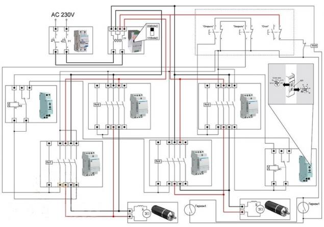
Electrical connectionsequipment Selectionmotor Control is performed according to the classic reverse pattern, but there is one detail. It is clear that the swing gate has a restrictive strap, so the leaf should emerge in a certain order. When tearing begins the first movement of the sash without straps, but closed it should last. This can be realized by different methods, the most reliable relays with switch-on delay.
Assembly of modular devices includes:
- four ES424 Hager contactor (4NO DC24V);
- two time switch Hager EZN001;
- circuit breaker Hager AD906J;
- power supply MeanWell DR-120–12.

Equipment is in plastic box Hager VECTOR VE118DN with degree of protection IP 65. The scheme is powered by two powerful motor-reducer IG-90GM under the voltage of 24V.
Through the differential relay power is supplied to terminals L and N of the power supply. With its back side removable, two lines 24 VDC, each feeds two coupled contacts for the input terminals of one of them the power is supplied in reverse polarity. The outputs of the pairs of contactors are connected in parallel and the voltage applied to the geared motor.
Secondary circuit and automaticcontrol Circuit contactor operates at a constant voltage of 24 V. the Positive power wire passes through the NC contacts of the stop button and connects to the normally closed contacts of the control buttons, from which the power is supplied to normally open contacts of the opposite buttons. With each button, voltage is supplied to two pairs of actuators, wherein one of the normally open contacts performs the function of the pickup coil. The control circuit of the direct actuator of the first pair and the reverse actuator opens the second pair of normally open relay. Power to relay is normally open contact of the starter of the other group. This configures the delay time for sequential movement of the valves.
Automatic stop of the engine is performed by the actuation of the limit reed switches. You need to install them along the direction of movement of the actuator, and the surface of the inner pipe to glue small neodymium magnets. Thus, when the actuator is fully built or stock in the extended state, is the operation of the reed switches, which short circuit power intermediate relays with normally closed contact. Relay connected in parallel and duplicate the "Stop"button.
The actuator can also be operated under the control of automation systems for swing gates, circuits similar. Now open the swing gate without leaving the car, you can easily and without major financial investments. published
P. S. And remember, only by changing their consumption — together we change the world! ©
Source: www.rmnt.ru/story/fences/905114.htm


The current status of solar energy in the conditions of U.S. households
Electro hatchback costs the Opel Ampera-e received a cruising range of 520 km