1047
Entertaining electricity
There is a lot of beeches and photo
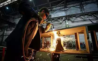
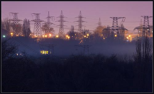
Many of us, residents of large cities, are often faced with an element of the urban landscape as a high voltage power lines. These mysterious elements of the industrial world carry something unusual, giving the impression of its power and rhythm of geometric interlacing.
Author - trainzer108.livejournal.com/5880.html
Today I will try to briefly tell you about how to run a high-voltage power grid, and what are some elements that we can find around. I must say - this is a brief description, and simplified some details omitted or simplified for better perception and understanding, so the experts in this area may notice some apparent flaws. This - not a technical manual, a popular description for those who are interested in the world of high-voltage transmission lines and power.
To begin conditionally divide the path of electricity from the source to the consumer on the conditional stages:
1.Vyrabotka (generation) of electricity.
2.Preobrazovanie and distribution of energy.
3.Peredacha energy.
4.Obratnoe conversion for later consumption or distribution.
5. Electricity consumption.
Implementation of the first tasks assigned to the sources of electrical energy - the power plant. The main part of any power - power generator driven by any external force - the vapor pressure in thermal power plants and nuclear power plants, hydroelectric water, the wind in the WEC, etc. Spinning in a magnetic field generator vybaratyvaet electricity in the windings of a current generator. Most often it is a three-phase alternating current. Let's take the example of hydroelectric scheme (GES):
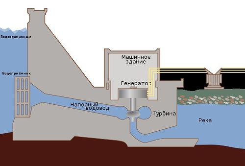
Water from the reservoir level is above the level of the river falls into the river down the penstocks, turning its flow turbine blades. Rotation of the turbine gives rise to a current in the generator, and it exits the plant.
As consumers of electricity are not in the territory of the power plant and at a distance from it, it would be logical that energy to pass them. To do this, we need to transform the energy - voltage from the generator power is not high enough to transmit electricity over long distances, and the current - on the contrary, is quite high, and the energy is quickly lost in the line of great extent, spending just on heating wires. We do not need, therefore, must be somehow reduce the current. In order for the same current capacity was lower, it is necessary to make the voltage is higher, which is what we're doing with the power transformers. This transformer is our top shemku with HPP is located on the right, gray, with horns. And he looks somewhere so:
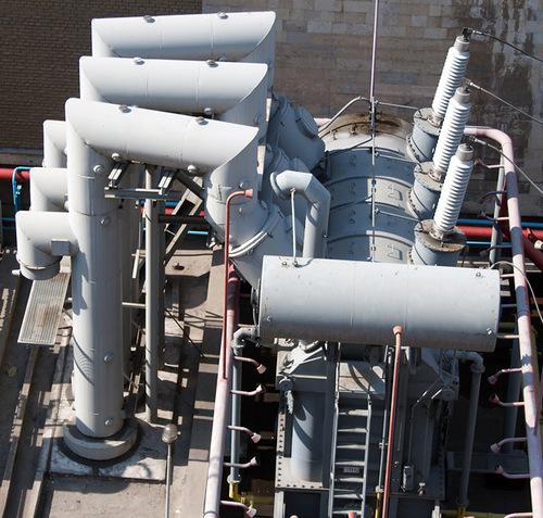
The greater the distance over which you want to transfer energy, the greater our need to make the voltage transformer. But there is a downside - the higher the voltage, the more expensive it becomes larger and heavier equipment for the conversion and transmission of energy. A compromise solution was the introduction of different voltage classes for different transmission distances - across the transmission over very long distances is overhead transmission lines (overhead lines) ultra-high voltage (750 or 500 kilovolts - between countries or in different parts of the country, 330 kV - between cities and energy systems) at a distance of less - the HV high-voltage (220, 150, 110 kV - between cities, sometimes within the city), between the districts of the town or city in the next villages - medium voltage (35 kV), in the district - 20, 10 and 6 kV, within a quarter or at home - 0.4 kW (380 V), inside the apartment - 0.2 kW (220 V).
Conversion of energy from one voltage level to another engaged in electrical substations and distribution and switching lines are engaged in the distribution unit (RU) of these substations. If the dispenser is located in the open air, it is called an open distribution device (ORU), and if the building - closed (LRU). The purpose of these devices - allocate different line voltage classes with each other, to make measurements of their characteristics, their switching and protection. For example, a substation may do one of three lines 330 kV 110 kV line or from two lines of 154 kV - 35 kV five lines. At the same time there is no specific direction of energy transfer - if (the latter case) power lines of 35 kV is not enough, it is to be sent to the line 154 kV (converted to 35 kV), and if the energy in the line of 35 kV in excess, then it is sent to the line 154 kV (converting 35 - & gt; 154 kV). The transfer direction in this case can be varied up to several times per second. Here is the substation switchyard:
Inside this vast forest of wires, poles and other piece of iron have some interesting priborchiki that help make the grid clearly functioning organism, able to control and regulate the distribution of energy. Let's look at them more closely to the example of a simple outdoor switchgear substation Dnieper-2. Increase his picture opening in the next tab - it will need us more.
In the already familiar to us the power transformer line come with electricity, who came directly from generators. His power - 13.8 kW (13800 B). After 220 in your outlet, this figure seems enormous, but it is not enough to transfer all the power our generators to us right away. We need to get 154 kV, and it is more than 10 times higher. That's why our 13.8 kV and enter the power transformer - it will help us get to the exit so we need 154 kV. Fulfill its a difficult, but very important work, the transformer produces a high-voltage line is already out, consisting of three phases - A, B and C. The voltage between the phases - 154 kV. The common point of generators is earthed, this is not always, but in this case it is so. Next, we need to measure the voltage to ensure proper operation of the power transformer. To do this, just to go to a phase voltage transformers. Further, for obtaining output values need to measure more power and current network. For this line comes to measuring current transformers. I recall that in the chain are connected in parallel voltmeters and ammeters - consistently, so voltage transformers have one input (in parallel), and current transformers - two since podklcheny series. It should also be noted that our large gray power transformer is protected by a fire extinguishing system automatically - a pink tube around it, from which the smaller tube.
Now go ahead and see it:
Right from our current transformers are located switches. They are slightly unlike the switches in your home, but the function they perform the same - allow you to quickly enable or disable the current in the circuit. Because we have a high voltage, there is a process of switching an electric arc (as in the electric ignition gas cookers, hot and bright "zipper") which may burn with switch electrodes. Therefore, there is a device inside the arc suppression by means of transformer oil. Such a switch is called a low-oil. There are more air, sulfur hexafluoride, just oil, but now is not important. What is important is that unlike your lamp switch, this switch its appearance not in any way suggests that in which it is now state - off or on. Look at him - how can you tell whether it is now more current? It is impossible, and this sadness we have to somehow fix it. To do this, right side with large and beautiful gray breakers, allowing even when there is no voltage in the circuit to reset the residual voltage, the circuit ground and visually show that the chain is broken. Look closely at the circuit breakers - they consist of two halves. When the isolator is connected and the circuit is turned on, the halves are joined, as our photos, like this: ----. And when he detached coupling and the circuit is broken, half disperse this way: | |. Disconnecting do not have any means of arc suppression, and are used for visual control of the United uchatskov line, switching can be carried out only in the absence of voltage! Otherwise, it will be here:
After all this, our electricity comes out the bus - a phase conductors, which connects several phases with several power transformers. This is done so that if one transformer is being repaired, then another, and then submits the line of electricity, and the light in the windows of the cozy town houses are still burning. Next to the bus three-phase power lines to come to the transmission distance. These three phases will continue to be called circuit power lines.
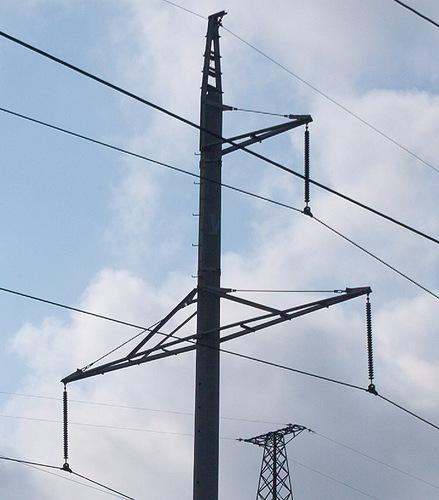
Now our energy is transferred to the stage of the transfer. And then we'll talk about the main elements of this link - for overhead lines and poles for them. Props can carry as one, and just two three-phase circuit - such support, respectively, are called single-circuit and double-circuit. That single-circuit support - bears the three phase conductors:
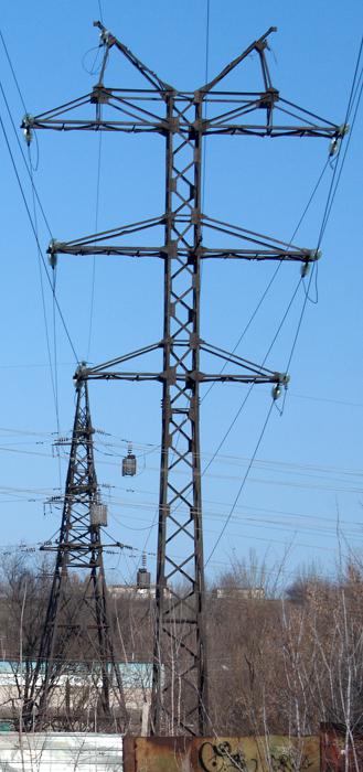
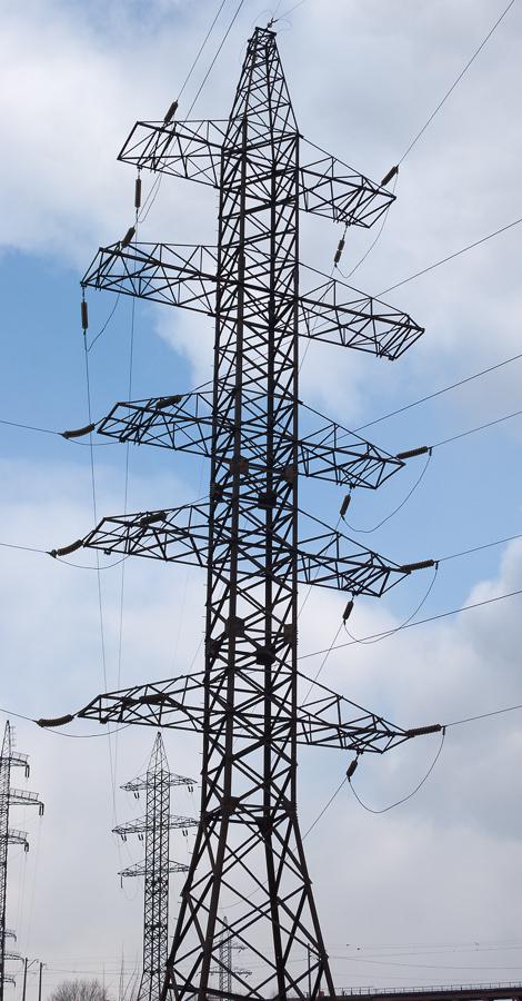
But this support - double-circuit, carries six phase conductors:
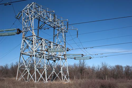
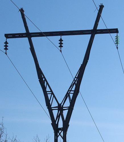
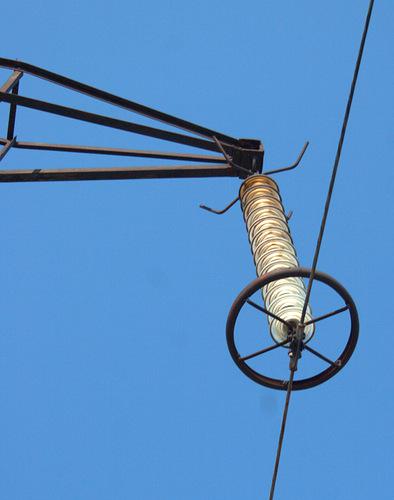
By appointment supports fall into the anchor and intermediate. Anchoring create tension, allow you to make a turn line (angular anchor supports), transferred through line barriers (transition anchor supports). A distinctive feature of anchor poles - Garland isolators parallel to the ground. Intermediate supports simply hold the wire above the ground, sensing the load from the weight of the wire and wind loads without creating tension wires. Intermediate supports are between the anchor, there may be many in a row, many transitional support are also intermediaries. On the intermediate supports garland insulator perpendicular to the surface of the earth. That anchor support, isolators parallel to the ground:
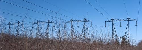
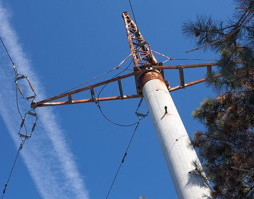
But intermediate supports, insulators look down:
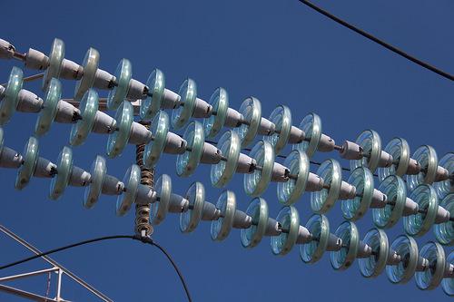
Each line has its own unique number, such as A10, L229, etc. These numbers, as well as the serial number of the support is usually applied to support themselves (numbering supports usually goes in the direction of the consumer or down substation). Insulators on the supports needed in order to secure the wire on the traverse and prevent electrical connection of phase conductors with the support. The more the insulators in the chain, the higher the voltage, or the more polluted the air in the area, or the greater weight of the wires have to keep the anchor support. By the number of insulators which is to define a class of line voltage - if the insulator 1, this line 6 or 10 kV, if in the chain of 3 to 5, this line with a voltage of 35 kV, if more than 5 insulators (10) - a 110 kV 8-12 insulators - 154 or 220 kV. Starting with the 330 kV conductor in phases rassheplyayutsya two not to use a very thick and heavy wire. It looks like this:
So if double wire, this 330 kW (with a few exceptions - can be cleaved and 154 kV, if the current line is very large). In phase 500 kV lines are split into three or four wires, and in lines 750 kV - 5 wires. Naturally, there is massive support themselves and larger.
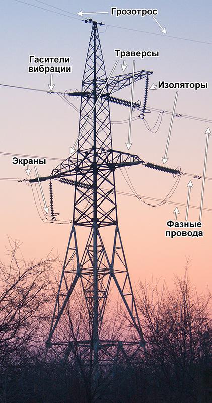
Now let's look at the structure supporting the power line and the accompanying electrical fittings. Here it is, the support (open this picture in a new tab, to continue to focus on it):
So if double wire, this 330 kW (with a few exceptions - can be cleaved and 154 kV, if the current line is very large). In phase 500 kV lines are split into three or four wires, and in lines 750 kV - 5 wires. Naturally, there is massive support themselves and larger.
Now let's look at the structure supporting the power line and the accompanying electrical fittings. Here it is, the support (open this picture in a new tab, to continue to focus on it):
Note that in some places the glass part of the insulator is not - it is evidence of the destruction of some of them. If there is the slightest crack prison, he immediately bursts and falls to the ground, according to the void in the chain could understand the need to change to a new detention center. Porcelain insulators glass a little easier, the color - dark brown. Here on this support 35 kV line on the left and in the center of porcelain insulators are located, and on the right - glass:
Polymeric insulators - very light, they are made of a material resembling soft plastic. Unlike other types of insulators, polymer produced in the form of ready to assemble garlands to the desired voltage class, while conventional insulators are going to a garland, connecting with each other using a special mounting system. With an equal creepage polymeric insulators have not only a lower weight, but also the overall dimensions - the very much thinner garland, and the number of edges in the chain is higher than for the same team a garland of glass or porcelain insulators. Here is the composite insulators on the support line of 35 KV:
And this is - composite insulators on the line 154 kV:
The attachment points of the phase wires to insulators on poles installed some metal rings called shields - they contribute to the uniform distribution of the electric field to reduce the corona discharge, which occurs in these areas, and reduce network losses on the crown. Corona discharge looks like a faint glow, followed by a crash - for power lines is harmful phenomenon and try to suppress it as much as possible. Protective screens have a different shape, there are many types - are in the form of rings, and in the form of half rings, and in the form of horns. For example, screens rings:
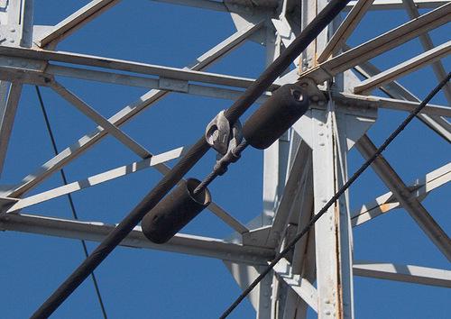
At the ends of the wires near the insulators are often located in the form design gantelek - vibration dampers. This is - an oscillating circuit tuned in anti-high-frequency oscillations of wires, and reducing their vibration, which can destroy the retaining valve and a wire in the place of attachment. Here's how they look closer:
At the top of any high-voltage support is attached a thin wire, called a ground wire. It is always located above the phase conductors, and decides if lightning hit the wire, or in support, she gets it in the ground wire, and will safely grounded through the support to bypass the phase conductors. Ground wire can be attached to the support through a single insulator, in some cases, he immediately mounted directly to the support, and more particularly to a steel rod that runs along the pole in the ground - the earth electrode.
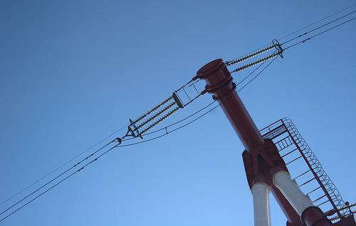
We now know some of the main elements of the transmission towers. Some of them, such as vibration dampers or screens do not occur at all supports, while others, such as traverse, insulators and ground wire - all without exception, as an integral part of the power line. In addition to the usual single and double-circuit towers there are also special. For example, here are carrying just three chains, in this case, it is made to change places of two chains:
There are also cases when the circuit must be separated from the main highway, for example, to enter the substation, or to create another line, while the main line will go further. This process is called a tap.
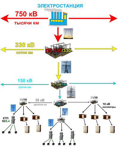
After the high voltage line has passed a certain path, it reaches a final or intermediate distribution substations, from which the other lines have usually a low voltage level. For example, came to power line voltage 750 kV, and, after a large area of the country has reached one of the substations in any major city. From this substation is already out several lines of 330 kV, and one of them, going from one big city to another, reached the substation, from which came out a few lines with a voltage, for example, 154 kV. In turn, one of the lines of 154 kV, having passed through the city in another region it reached the substation, from which a few lines of 35 kV. One of these lines runs through the district of the city, it comes to the district substation where it is converted into a variety of distribution lines with voltage of 10 kV. Each of these lines, and there is a quarterly district (under the ground, if it is an area of high-rise buildings, and in the air, if the private sector). In turn, our line of 10 kV in the quarter-purpose line by means of a transformer substation (TS - if it is high-rise developments quarter), and complete transformer substations (CRL - if it is the private sector) is converted into a line of 0.4 kW (380 V). This three-phase network is distributed on the floors of homes or homes in the private sector - one phase in each house, phase alternating sequence. Below is a diagram conditionally illustrated as lines of different classes are distributed along the path from the voltage power to end users. The scheme increased by clicking.
Source:
Many of us, residents of large cities, are often faced with an element of the urban landscape as a high voltage power lines. These mysterious elements of the industrial world carry something unusual, giving the impression of its power and rhythm of geometric interlacing.
Author - trainzer108.livejournal.com/5880.html

Today I will try to briefly tell you about how to run a high-voltage power grid, and what are some elements that we can find around. I must say - this is a brief description, and simplified some details omitted or simplified for better perception and understanding, so the experts in this area may notice some apparent flaws. This - not a technical manual, a popular description for those who are interested in the world of high-voltage transmission lines and power.
To begin conditionally divide the path of electricity from the source to the consumer on the conditional stages:
1.Vyrabotka (generation) of electricity.
2.Preobrazovanie and distribution of energy.
3.Peredacha energy.
4.Obratnoe conversion for later consumption or distribution.
5. Electricity consumption.
Implementation of the first tasks assigned to the sources of electrical energy - the power plant. The main part of any power - power generator driven by any external force - the vapor pressure in thermal power plants and nuclear power plants, hydroelectric water, the wind in the WEC, etc. Spinning in a magnetic field generator vybaratyvaet electricity in the windings of a current generator. Most often it is a three-phase alternating current. Let's take the example of hydroelectric scheme (GES):

Water from the reservoir level is above the level of the river falls into the river down the penstocks, turning its flow turbine blades. Rotation of the turbine gives rise to a current in the generator, and it exits the plant.
As consumers of electricity are not in the territory of the power plant and at a distance from it, it would be logical that energy to pass them. To do this, we need to transform the energy - voltage from the generator power is not high enough to transmit electricity over long distances, and the current - on the contrary, is quite high, and the energy is quickly lost in the line of great extent, spending just on heating wires. We do not need, therefore, must be somehow reduce the current. In order for the same current capacity was lower, it is necessary to make the voltage is higher, which is what we're doing with the power transformers. This transformer is our top shemku with HPP is located on the right, gray, with horns. And he looks somewhere so:

The greater the distance over which you want to transfer energy, the greater our need to make the voltage transformer. But there is a downside - the higher the voltage, the more expensive it becomes larger and heavier equipment for the conversion and transmission of energy. A compromise solution was the introduction of different voltage classes for different transmission distances - across the transmission over very long distances is overhead transmission lines (overhead lines) ultra-high voltage (750 or 500 kilovolts - between countries or in different parts of the country, 330 kV - between cities and energy systems) at a distance of less - the HV high-voltage (220, 150, 110 kV - between cities, sometimes within the city), between the districts of the town or city in the next villages - medium voltage (35 kV), in the district - 20, 10 and 6 kV, within a quarter or at home - 0.4 kW (380 V), inside the apartment - 0.2 kW (220 V).
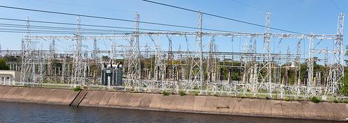
Conversion of energy from one voltage level to another engaged in electrical substations and distribution and switching lines are engaged in the distribution unit (RU) of these substations. If the dispenser is located in the open air, it is called an open distribution device (ORU), and if the building - closed (LRU). The purpose of these devices - allocate different line voltage classes with each other, to make measurements of their characteristics, their switching and protection. For example, a substation may do one of three lines 330 kV 110 kV line or from two lines of 154 kV - 35 kV five lines. At the same time there is no specific direction of energy transfer - if (the latter case) power lines of 35 kV is not enough, it is to be sent to the line 154 kV (converted to 35 kV), and if the energy in the line of 35 kV in excess, then it is sent to the line 154 kV (converting 35 - & gt; 154 kV). The transfer direction in this case can be varied up to several times per second. Here is the substation switchyard:

Inside this vast forest of wires, poles and other piece of iron have some interesting priborchiki that help make the grid clearly functioning organism, able to control and regulate the distribution of energy. Let's look at them more closely to the example of a simple outdoor switchgear substation Dnieper-2. Increase his picture opening in the next tab - it will need us more.

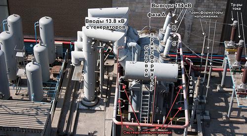
In the already familiar to us the power transformer line come with electricity, who came directly from generators. His power - 13.8 kW (13800 B). After 220 in your outlet, this figure seems enormous, but it is not enough to transfer all the power our generators to us right away. We need to get 154 kV, and it is more than 10 times higher. That's why our 13.8 kV and enter the power transformer - it will help us get to the exit so we need 154 kV. Fulfill its a difficult, but very important work, the transformer produces a high-voltage line is already out, consisting of three phases - A, B and C. The voltage between the phases - 154 kV. The common point of generators is earthed, this is not always, but in this case it is so. Next, we need to measure the voltage to ensure proper operation of the power transformer. To do this, just to go to a phase voltage transformers. Further, for obtaining output values need to measure more power and current network. For this line comes to measuring current transformers. I recall that in the chain are connected in parallel voltmeters and ammeters - consistently, so voltage transformers have one input (in parallel), and current transformers - two since podklcheny series. It should also be noted that our large gray power transformer is protected by a fire extinguishing system automatically - a pink tube around it, from which the smaller tube.
Now go ahead and see it:

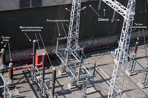
Right from our current transformers are located switches. They are slightly unlike the switches in your home, but the function they perform the same - allow you to quickly enable or disable the current in the circuit. Because we have a high voltage, there is a process of switching an electric arc (as in the electric ignition gas cookers, hot and bright "zipper") which may burn with switch electrodes. Therefore, there is a device inside the arc suppression by means of transformer oil. Such a switch is called a low-oil. There are more air, sulfur hexafluoride, just oil, but now is not important. What is important is that unlike your lamp switch, this switch its appearance not in any way suggests that in which it is now state - off or on. Look at him - how can you tell whether it is now more current? It is impossible, and this sadness we have to somehow fix it. To do this, right side with large and beautiful gray breakers, allowing even when there is no voltage in the circuit to reset the residual voltage, the circuit ground and visually show that the chain is broken. Look closely at the circuit breakers - they consist of two halves. When the isolator is connected and the circuit is turned on, the halves are joined, as our photos, like this: ----. And when he detached coupling and the circuit is broken, half disperse this way: | |. Disconnecting do not have any means of arc suppression, and are used for visual control of the United uchatskov line, switching can be carried out only in the absence of voltage! Otherwise, it will be here:
After all this, our electricity comes out the bus - a phase conductors, which connects several phases with several power transformers. This is done so that if one transformer is being repaired, then another, and then submits the line of electricity, and the light in the windows of the cozy town houses are still burning. Next to the bus three-phase power lines to come to the transmission distance. These three phases will continue to be called circuit power lines.
Now our energy is transferred to the stage of the transfer. And then we'll talk about the main elements of this link - for overhead lines and poles for them. Props can carry as one, and just two three-phase circuit - such support, respectively, are called single-circuit and double-circuit. That single-circuit support - bears the three phase conductors:

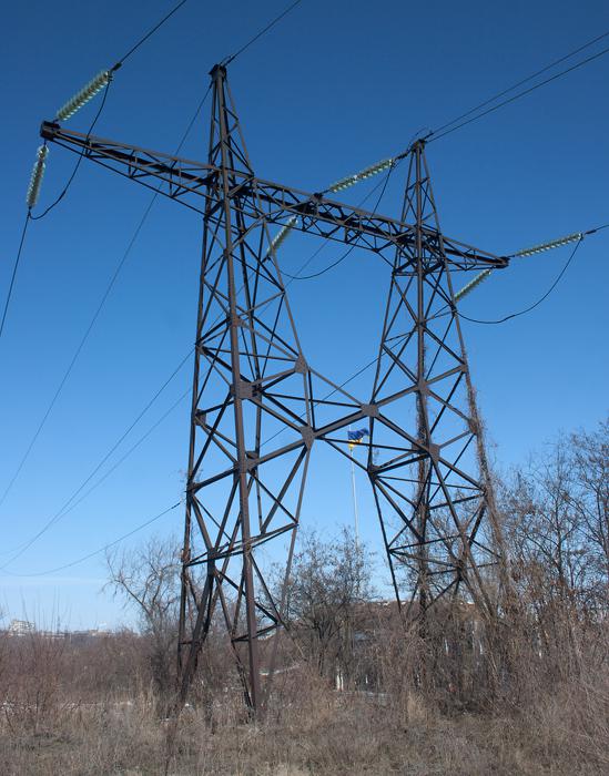
But this support - double-circuit, carries six phase conductors:

By appointment supports fall into the anchor and intermediate. Anchoring create tension, allow you to make a turn line (angular anchor supports), transferred through line barriers (transition anchor supports). A distinctive feature of anchor poles - Garland isolators parallel to the ground. Intermediate supports simply hold the wire above the ground, sensing the load from the weight of the wire and wind loads without creating tension wires. Intermediate supports are between the anchor, there may be many in a row, many transitional support are also intermediaries. On the intermediate supports garland insulator perpendicular to the surface of the earth. That anchor support, isolators parallel to the ground:

But intermediate supports, insulators look down:

Each line has its own unique number, such as A10, L229, etc. These numbers, as well as the serial number of the support is usually applied to support themselves (numbering supports usually goes in the direction of the consumer or down substation). Insulators on the supports needed in order to secure the wire on the traverse and prevent electrical connection of phase conductors with the support. The more the insulators in the chain, the higher the voltage, or the more polluted the air in the area, or the greater weight of the wires have to keep the anchor support. By the number of insulators which is to define a class of line voltage - if the insulator 1, this line 6 or 10 kV, if in the chain of 3 to 5, this line with a voltage of 35 kV, if more than 5 insulators (10) - a 110 kV 8-12 insulators - 154 or 220 kV. Starting with the 330 kV conductor in phases rassheplyayutsya two not to use a very thick and heavy wire. It looks like this:

So if double wire, this 330 kW (with a few exceptions - can be cleaved and 154 kV, if the current line is very large). In phase 500 kV lines are split into three or four wires, and in lines 750 kV - 5 wires. Naturally, there is massive support themselves and larger.
Now let's look at the structure supporting the power line and the accompanying electrical fittings. Here it is, the support (open this picture in a new tab, to continue to focus on it):

Note that in some places the glass part of the insulator is not - it is evidence of the destruction of some of them. If there is the slightest crack prison, he immediately bursts and falls to the ground, according to the void in the chain could understand the need to change to a new detention center. Porcelain insulators glass a little easier, the color - dark brown. Here on this support 35 kV line on the left and in the center of porcelain insulators are located, and on the right - glass:

Polymeric insulators - very light, they are made of a material resembling soft plastic. Unlike other types of insulators, polymer produced in the form of ready to assemble garlands to the desired voltage class, while conventional insulators are going to a garland, connecting with each other using a special mounting system. With an equal creepage polymeric insulators have not only a lower weight, but also the overall dimensions - the very much thinner garland, and the number of edges in the chain is higher than for the same team a garland of glass or porcelain insulators. Here is the composite insulators on the support line of 35 KV:

And this is - composite insulators on the line 154 kV:

The attachment points of the phase wires to insulators on poles installed some metal rings called shields - they contribute to the uniform distribution of the electric field to reduce the corona discharge, which occurs in these areas, and reduce network losses on the crown. Corona discharge looks like a faint glow, followed by a crash - for power lines is harmful phenomenon and try to suppress it as much as possible. Protective screens have a different shape, there are many types - are in the form of rings, and in the form of half rings, and in the form of horns. For example, screens rings:

At the ends of the wires near the insulators are often located in the form design gantelek - vibration dampers. This is - an oscillating circuit tuned in anti-high-frequency oscillations of wires, and reducing their vibration, which can destroy the retaining valve and a wire in the place of attachment. Here's how they look closer:

At the top of any high-voltage support is attached a thin wire, called a ground wire. It is always located above the phase conductors, and decides if lightning hit the wire, or in support, she gets it in the ground wire, and will safely grounded through the support to bypass the phase conductors. Ground wire can be attached to the support through a single insulator, in some cases, he immediately mounted directly to the support, and more particularly to a steel rod that runs along the pole in the ground - the earth electrode.
We now know some of the main elements of the transmission towers. Some of them, such as vibration dampers or screens do not occur at all supports, while others, such as traverse, insulators and ground wire - all without exception, as an integral part of the power line. In addition to the usual single and double-circuit towers there are also special. For example, here are carrying just three chains, in this case, it is made to change places of two chains:

There are also cases when the circuit must be separated from the main highway, for example, to enter the substation, or to create another line, while the main line will go further. This process is called a tap.
After the high voltage line has passed a certain path, it reaches a final or intermediate distribution substations, from which the other lines have usually a low voltage level. For example, came to power line voltage 750 kV, and, after a large area of the country has reached one of the substations in any major city. From this substation is already out several lines of 330 kV, and one of them, going from one big city to another, reached the substation, from which came out a few lines with a voltage, for example, 154 kV. In turn, one of the lines of 154 kV, having passed through the city in another region it reached the substation, from which a few lines of 35 kV. One of these lines runs through the district of the city, it comes to the district substation where it is converted into a variety of distribution lines with voltage of 10 kV. Each of these lines, and there is a quarterly district (under the ground, if it is an area of high-rise buildings, and in the air, if the private sector). In turn, our line of 10 kV in the quarter-purpose line by means of a transformer substation (TS - if it is high-rise developments quarter), and complete transformer substations (CRL - if it is the private sector) is converted into a line of 0.4 kW (380 V). This three-phase network is distributed on the floors of homes or homes in the private sector - one phase in each house, phase alternating sequence. Below is a diagram conditionally illustrated as lines of different classes are distributed along the path from the voltage power to end users. The scheme increased by clicking.

Source: