Good afternoon, habrovchane.
This post will be a bit unusual.
In it, I'll show you how to make a simple and powerful enough high voltage generator (280,000 volts). I took as a basis for the scheme
генератора Marx . Feature my circuit that I counted under her available and inexpensive parts. By the same scheme itself easy to repeat (I have to build it took 15 minutes), requires no configuration and run the first time. In my opinion a lot easier than the Tesla transformer or voltage multiplier Cockcroft-Walton.
How it works h4>
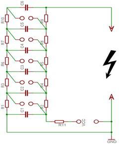
Immediately after the start charging capacitor. In my case, up to 35 kilovolts. As soon as the voltage reaches the breakdown threshold of one of the fuses, capacitors connected in series through the gap, resulting in a doubling of voltage across the capacitor is connected to this surge. Because of this, almost instantly triggered spark gaps and the voltage remaining on the capacitors formed. I used the 12 steps, that is, the voltage should be multiplied by 12 (12 x 35 = 420). 420 kilovolts is almost half-meter level. But in practice, taking into account all losses, get bits length of 28 cm. The losses were a consequence of corona discharges.

The details: h4>
The scheme itself is simple, consisting of capacitors, resistors and fuses. More need power supply. Since all parts high, the question arises, where do they get it? Now, first things first:
1 - Resistors h5>
Need resistors 100 ohm, 5 watt, 50,000 volts.
I have tried many factory resistors, but not one could not stand the strain - arc punched over the body, and nothing worked. Careful zaguglivanie gave an unexpected answer: the master who collected Marx generator voltage more than 100,000 volts, used complex fluid resistors Marx generator on liquid resistors or use a lot of steps. I wanted something simpler and resistors made of wood.
Broke off the street two smooth branches of raw tree (dry no current holds) and included the first branch in place of the resistor with the right of the capacitor, a second branch in place of the resistor to the left of the capacitors. Get two branches with a plurality of terminals at regular intervals. Conclusions I have done by winding a bare wire over the branches. Experience shows that such resistors withstand voltage of tens of megavolt (10 million volts)
2 - capacitors h5>
Everything is easier. I took the capacitors that were the cheapest on the radio market - K15-4, 470 pF, 30 kV, (they grinshity). They were used in the tube televisions, so now you can buy them for dismantling or to request free of charge. Voltage of 35 kV, they kept well, no one struck.
3 - power supply h5>
Collect a separate circuit for the power of my Marx generator I simply not raised a hand. Because the other day I gave a neighbor old TV "Electron SC-451." At the anode tube in the color TVs use a DC voltage of about 27,000 volts. I disconnected the high-voltage wire (sucker), with the tube anode and decided to see what the arc voltage gain from this.
// www.youtube.com/embed/VQ9Ay0hylqg?wmode=opaque video>
Plenty enough arc, came to the conclusion that the scheme of the TV is quite stable, easily withstand overload and short-circuit current protection trips and nothing burns. The scheme of the TV has headroom and I managed to overclock it from 27 to 35 kilovolts. For this, I twisted podstroichnik R2 in the power supply module of the TV so that the power in the line scan has risen from 125 to 150 volts, which in turn led to an increase in the anode voltage of 35 kV. If you attempt to further increase the voltage, the transistor KT838A breaks in horizontal sweep of the TV, so you should not overdo it.
The build process h4>
With copper wire I screwed capacitors to the branches of a tree. Between the capacitors should be a distance of 37 mm, or you may be undesirable breakdown. The free ends of the wire I bent in such a way that would get between 30 mm - it will arresters.
Better to see once than to hear 100 times. Watch the video, where I showed in detail the process of assembly and operation of the generator:
// www.youtube.com/embed/lRgYai6FlCQ?wmode=opaque video>
Safety h4>
Need to be especially careful, since the circuit operates at a constant voltage and discharge even from one capacitor, is likely to be fatal. When the scheme must be sufficiently distant because electricity breaks through the air 20 cm or more. After each shutdown a must discharge all capacitors (even the ones that are on TV), well-grounded conductor.
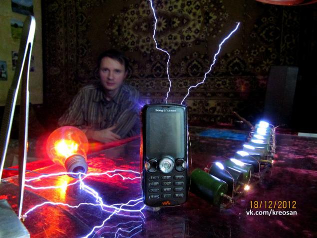
Better out of the room, where they will conduct experiments, remove all the electronics. Discharges create powerful electromagnetic pulses. Phone, keyboard and monitor, as shown in my video, out of order and repair are no longer subject! Even in the next room I turned off the gas boiler.
Need to protect your hearing. Noise from the ranks like the shots, then from his ears ringing.
Interesting observations h4>
The first thing you feel when you turn, how electrified the air in the room. The electric field strength at much high that is felt every hair body.
Clearly visible corona discharge. Beautiful bluish glow around the parts and wires.
Constantly slightly beats the current, sometimes you do not understand on what has touched to the door - slipped spark wanted to take a pair of scissors - shot by scissors. In the dark noticed that spark skips between different metal objects that are not connected to the generator: in diplomacy with the tool slipped sparks between screwdrivers, pliers, soldering iron.
Light bulbs themselves, without wires.
Ozone smell throughout the house, as after a thunderstorm.
Conclusion h4>
All items will cost somewhere in the 50 UAH ($ 5), it is an old TV and capacitors. Now I'm developing a brand new scheme in order to inexpensively obtain meter level. You may ask: how the application of this scheme? My answer is that the application is, but you need to discuss them in a different theme.
At the same time I still use caution when working with high voltage.
Source: habrahabr.ru/post/212997/


