862
Thermoacoustic engine – a Stirling engine without pistons
Stirling engine – an engine with an external supply of heat. External heat supply is very handy when you want to use as a heat source, not fossil fuels. For example, you can use solar energy, geothermal energy, heat from the knockdown of various enterprises.
A nice feature of the Stirling cycle is that its efficiency is equal to efficiency of Carnot cycle [1]. Of course the real Stirling engines the efficiency is lower, and often much. The Stirling engine began its existence with a device that has many moving parts such as pistons, rods, crankshaft, bearings. In addition, also the rotor of the generator is spun (figure 1).
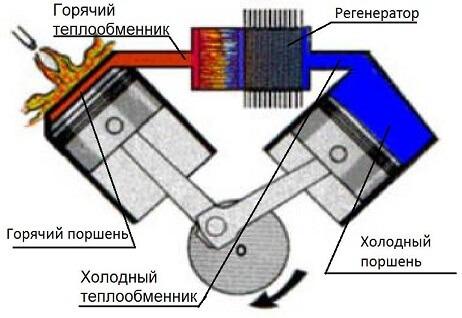
Figure 1 – Stirling Engine alpha type
View the Stirling engine alpha type. When the shaft rotates the pistons begin to distill the gas from a cold to a hot cylinder, on the contrary, from hot to cold. But they are not just distilled, but also compress and expand. Performed thermodynamic cycle. You can imagine the picture that when the shaft rotate so that the axis on which are mounted the connecting rods will be at the top, it will be the moment of greatest compression of the gas, and when at the bottom, the extension. However this is not quite true due to thermal expansion and contraction of the gas, but roughly all the same all it is.
The heart of the engine is the so-called core, which consists of two heat exchangers – hot and cold and in between there is a regenerator. Heat exchangers are usually made of plate, and the regenerator is most often a stack formed from a metal mesh. Why is it necessary to clear heat exchangers – heating and cooling gas, and why you need a regenerator? A regenerator is present the heat accumulator. When the hot gas moves to the cold side, it heats the regenerator and the regenerator stores heat energy. When the gas moves from the cold to hot side, the cold gas is heated in the regenerator and thus it's warmth without a regenerator would have gone into heating the environment, it saved. So, the regenerator is a very necessary thing. A good regenerator increases the efficiency of the engine approximately in 3.6 times.
Lovers, who dream to build a similar engine yourself, you want to talk more about the heat exchangers. Most homemade Stirling engines, of those that I have seen do not have the heat exchangers (I'm talking about the engines of the alpha type). The heat exchangers themselves are the pistons and cylinders. One cylinder is heated, the other cooled. The heat exchange surface area in contact with the gas is quite small. So, it is possible to significantly increase the engine power by putting at the entrance of the cylinders heat exchangers. And even in figure 1, the flame is directed straight to the cylinder that the factory engines are not quite so.
Back to the history of Stirling engines. So, let the engine largely good, but the presence of piston oil rings and bearings reduces the life of the engine and the engineers thought for how to improve it, and came up with.
In 1969, William Bayle investigated resonance effects in the engine and was later able to make an engine that does not need neither the connecting rods nor crankshaft. Synchronization of the pistons was due to resonance effects. This type of engine was called the free piston engine (figure 2).
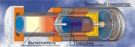
Figure 2 – free piston Stirling engine
Figure 2 shows a free piston engine beta type. Here the gas is transferred from hot region to cold and Vice versa, thanks to the displacer (which moves freely), and the working piston performs useful work. The displacer and the piston oscillate coil-spring, which you can see in the right side of the figure. The difficulty is that their swings should be with the same frequency and with a phase difference of 90 degrees and it's all thanks to resonance effects. Make it pretty difficult.
Thus, the number of parts reduced, but the tightened requirements for the accuracy of the calculations and workmanship. But engine reliability has undoubtedly increased, especially in constructions where the displacer piston and the flexible membrane. In this case, the engine in General there are no rubbing parts. Electricity, if desired, such an engine can be removed with a linear generator.
But this engineers was not enough and they began to look for ways to get rid not just from friction parts, but in General from moving parts. And they found a way around it.
In the seventies of the 20th century Peter was Ceperly realized that sinusoidal pressure and gas velocity in the Stirling engine, and the fact that these oscillations are in phase, incredibly strongly reminiscent of the pressure fluctuations and gas velocity in a traveling sound wave (Fig.3).
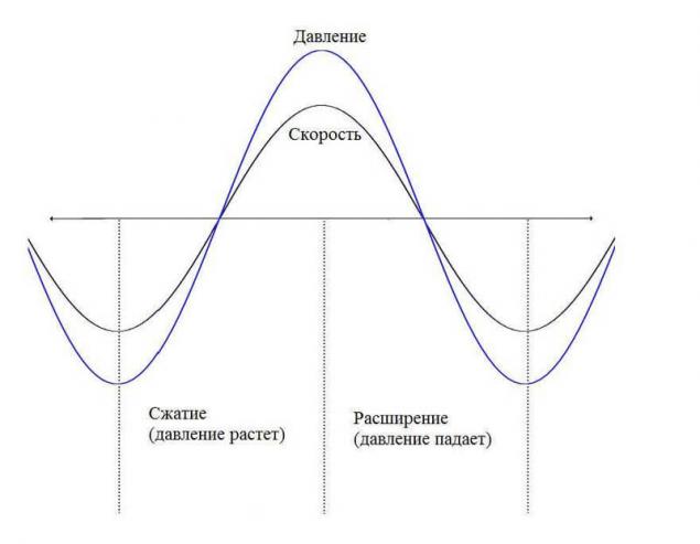
Figure 3 — Graph of pressure and velocity of traveling acoustic waves as a function of time. It is shown that the fluctuations of pressure and velocity are in phase.
This idea came Ceperly no coincidence, as it was a lot of research in the field of termoacustici, for example, Lord Rayleigh in 1884 qualitatively describe this phenomenon.
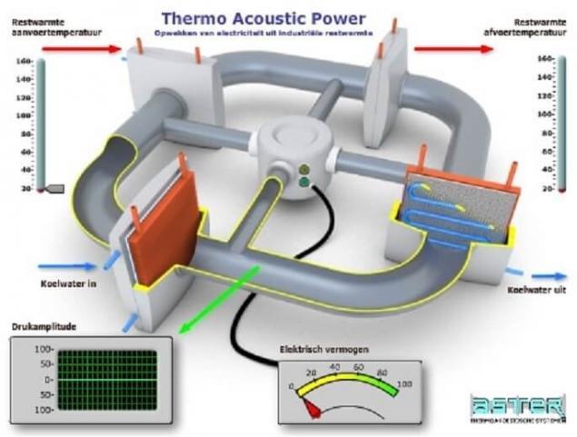
Thus, it is suggested to opt out of the pistons and displacers, and use only acoustic waves to control pressure and gas flow. This gives the engine without moving parts and theoretically able to achieve efficiency of the Stirling cycle, and hence Carnot. In reality, the best performance is 40-50 % of the efficiency of the Carnot cycle (figure 4).
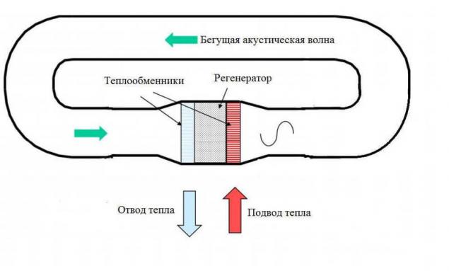
Figure 4 – diagram of the thermoacoustic engine with a traveling wave
You can see that the thermoacoustic engine with a traveling wave is exactly the same-consisting of heat exchangers and regenerator, but instead of the pistons and connecting rods here, just a looped tube, which is called the resonator. But how this engine works, if there are no moving parts? How is that possible?
To begin to answer the question, where there is sound? And the answer is – it arises by itself when experiencing a sufficient temperature difference between two heat exchangers. The temperature gradient in the regenerator allows you to enhance the sound vibrations, but only of a specific wavelength equal to the length of the resonator. From the outset, the process looks like: when heated hot heat exchanger there are micro noises, possibly crackling of thermal deformation, it is inevitable. These noises is the noise having a wide frequency range. Out of this rich spectrum of sound frequencies, the engine begins to amplify the sound fluctuation, the wavelength of which is equal to the length of the pipe resonator. And no matter how small the initial oscillation, it will be enhanced to the maximum possible value. The maximum volume of the sound inside the engine occurs when the capacity of sound amplification with the help of heat exchangers equal to the power loss, i.e. power attenuation of sound vibrations. And the maximum value sometimes reaches enormous quantities in 160 dB. So inside such an engine really loud. Fortunately, the sound output can not leave, because the resonator is sealed and on this, standing next to a running engine, its barely audible.
The gain of a certain frequency of sound is due to the same thermodynamic cycle – Stirling cycle, which is carried out in the regenerator.
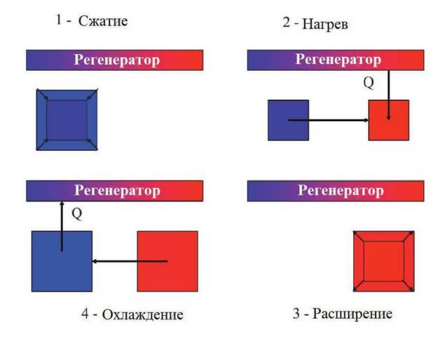
Figure 5 – Stage cycle roughly and simplistically.
As I wrote in thermoacoustic engine at all no moving parts, it only generates an acoustic wave inside itself, but, unfortunately, with no moving parts to remove the electric motor impossible.
Typically extract energy from the thermoacoustic engines with linear generators. Elastic membrane oscillates under the pressure of sound waves of high intensity. Inside the copper coil with a core mounted on the vibrating membrane magnets. Generating electricity.
In 2014 Kees de Blok, Pawel Owczarek and Maurice Francois from enterprise, Aster Thermoacoustics showed that to convert the energy of sound waves into electricity, suitable bi-directional impulse turbine connected to a generator.
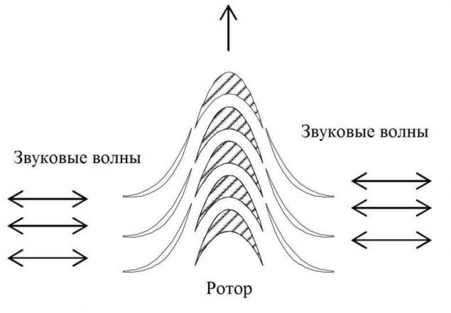
Figure 6 – Diagram of impulse turbine
Impulse turbine spins in the same direction regardless of flow direction. Figure 6 schematically shows the stator vanes on the sides and the blades of the rotor in the middle.
And so turbine looks at them in reality:
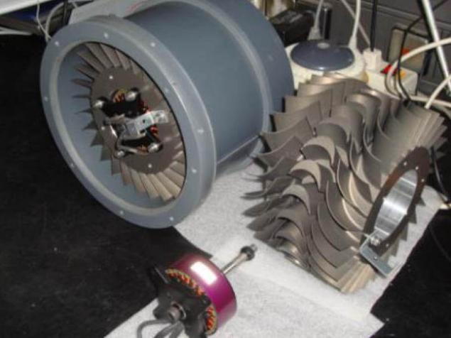
Figure 7 – External view of bi-directional impulse turbines
It is expected that the use of turbine instead of a linear generator will greatly reduce the cost of construction and will increase the capacity of the device up to the capacity of a typical CHP plant, which is not possible with linear generators. published
P. S. And remember, only by changing their consumption — together we change the world! ©
Source: geektimes.ru/post/287578/

A nice feature of the Stirling cycle is that its efficiency is equal to efficiency of Carnot cycle [1]. Of course the real Stirling engines the efficiency is lower, and often much. The Stirling engine began its existence with a device that has many moving parts such as pistons, rods, crankshaft, bearings. In addition, also the rotor of the generator is spun (figure 1).

Figure 1 – Stirling Engine alpha type
View the Stirling engine alpha type. When the shaft rotates the pistons begin to distill the gas from a cold to a hot cylinder, on the contrary, from hot to cold. But they are not just distilled, but also compress and expand. Performed thermodynamic cycle. You can imagine the picture that when the shaft rotate so that the axis on which are mounted the connecting rods will be at the top, it will be the moment of greatest compression of the gas, and when at the bottom, the extension. However this is not quite true due to thermal expansion and contraction of the gas, but roughly all the same all it is.
The heart of the engine is the so-called core, which consists of two heat exchangers – hot and cold and in between there is a regenerator. Heat exchangers are usually made of plate, and the regenerator is most often a stack formed from a metal mesh. Why is it necessary to clear heat exchangers – heating and cooling gas, and why you need a regenerator? A regenerator is present the heat accumulator. When the hot gas moves to the cold side, it heats the regenerator and the regenerator stores heat energy. When the gas moves from the cold to hot side, the cold gas is heated in the regenerator and thus it's warmth without a regenerator would have gone into heating the environment, it saved. So, the regenerator is a very necessary thing. A good regenerator increases the efficiency of the engine approximately in 3.6 times.
Lovers, who dream to build a similar engine yourself, you want to talk more about the heat exchangers. Most homemade Stirling engines, of those that I have seen do not have the heat exchangers (I'm talking about the engines of the alpha type). The heat exchangers themselves are the pistons and cylinders. One cylinder is heated, the other cooled. The heat exchange surface area in contact with the gas is quite small. So, it is possible to significantly increase the engine power by putting at the entrance of the cylinders heat exchangers. And even in figure 1, the flame is directed straight to the cylinder that the factory engines are not quite so.
Back to the history of Stirling engines. So, let the engine largely good, but the presence of piston oil rings and bearings reduces the life of the engine and the engineers thought for how to improve it, and came up with.
In 1969, William Bayle investigated resonance effects in the engine and was later able to make an engine that does not need neither the connecting rods nor crankshaft. Synchronization of the pistons was due to resonance effects. This type of engine was called the free piston engine (figure 2).

Figure 2 – free piston Stirling engine
Figure 2 shows a free piston engine beta type. Here the gas is transferred from hot region to cold and Vice versa, thanks to the displacer (which moves freely), and the working piston performs useful work. The displacer and the piston oscillate coil-spring, which you can see in the right side of the figure. The difficulty is that their swings should be with the same frequency and with a phase difference of 90 degrees and it's all thanks to resonance effects. Make it pretty difficult.
Thus, the number of parts reduced, but the tightened requirements for the accuracy of the calculations and workmanship. But engine reliability has undoubtedly increased, especially in constructions where the displacer piston and the flexible membrane. In this case, the engine in General there are no rubbing parts. Electricity, if desired, such an engine can be removed with a linear generator.
But this engineers was not enough and they began to look for ways to get rid not just from friction parts, but in General from moving parts. And they found a way around it.
In the seventies of the 20th century Peter was Ceperly realized that sinusoidal pressure and gas velocity in the Stirling engine, and the fact that these oscillations are in phase, incredibly strongly reminiscent of the pressure fluctuations and gas velocity in a traveling sound wave (Fig.3).

Figure 3 — Graph of pressure and velocity of traveling acoustic waves as a function of time. It is shown that the fluctuations of pressure and velocity are in phase.
This idea came Ceperly no coincidence, as it was a lot of research in the field of termoacustici, for example, Lord Rayleigh in 1884 qualitatively describe this phenomenon.
Thus, it is suggested to opt out of the pistons and displacers, and use only acoustic waves to control pressure and gas flow. This gives the engine without moving parts and theoretically able to achieve efficiency of the Stirling cycle, and hence Carnot. In reality, the best performance is 40-50 % of the efficiency of the Carnot cycle (figure 4).

Figure 4 – diagram of the thermoacoustic engine with a traveling wave
You can see that the thermoacoustic engine with a traveling wave is exactly the same-consisting of heat exchangers and regenerator, but instead of the pistons and connecting rods here, just a looped tube, which is called the resonator. But how this engine works, if there are no moving parts? How is that possible?
To begin to answer the question, where there is sound? And the answer is – it arises by itself when experiencing a sufficient temperature difference between two heat exchangers. The temperature gradient in the regenerator allows you to enhance the sound vibrations, but only of a specific wavelength equal to the length of the resonator. From the outset, the process looks like: when heated hot heat exchanger there are micro noises, possibly crackling of thermal deformation, it is inevitable. These noises is the noise having a wide frequency range. Out of this rich spectrum of sound frequencies, the engine begins to amplify the sound fluctuation, the wavelength of which is equal to the length of the pipe resonator. And no matter how small the initial oscillation, it will be enhanced to the maximum possible value. The maximum volume of the sound inside the engine occurs when the capacity of sound amplification with the help of heat exchangers equal to the power loss, i.e. power attenuation of sound vibrations. And the maximum value sometimes reaches enormous quantities in 160 dB. So inside such an engine really loud. Fortunately, the sound output can not leave, because the resonator is sealed and on this, standing next to a running engine, its barely audible.
The gain of a certain frequency of sound is due to the same thermodynamic cycle – Stirling cycle, which is carried out in the regenerator.

Figure 5 – Stage cycle roughly and simplistically.
As I wrote in thermoacoustic engine at all no moving parts, it only generates an acoustic wave inside itself, but, unfortunately, with no moving parts to remove the electric motor impossible.
Typically extract energy from the thermoacoustic engines with linear generators. Elastic membrane oscillates under the pressure of sound waves of high intensity. Inside the copper coil with a core mounted on the vibrating membrane magnets. Generating electricity.
In 2014 Kees de Blok, Pawel Owczarek and Maurice Francois from enterprise, Aster Thermoacoustics showed that to convert the energy of sound waves into electricity, suitable bi-directional impulse turbine connected to a generator.

Figure 6 – Diagram of impulse turbine
Impulse turbine spins in the same direction regardless of flow direction. Figure 6 schematically shows the stator vanes on the sides and the blades of the rotor in the middle.
And so turbine looks at them in reality:

Figure 7 – External view of bi-directional impulse turbines
It is expected that the use of turbine instead of a linear generator will greatly reduce the cost of construction and will increase the capacity of the device up to the capacity of a typical CHP plant, which is not possible with linear generators. published
P. S. And remember, only by changing their consumption — together we change the world! ©
Source: geektimes.ru/post/287578/
Anti-aging exercises for eyes: get rid of puffiness and wrinkles!
Graphene electrodes enhance the battery capacity of 3000%
