858
Combined solar collectors with heat pipes
Solar energy used to produce hot water (warm air) and generation of electrical energy. Electrical energy is produced using photovoltaic panels. The resulting electric energy is used for industrial purposes and individual power supply.
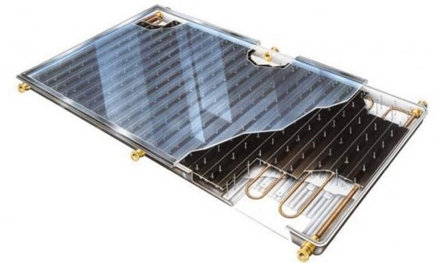
Solar collectors and water heaters represent heat exchangers made in the form of a conventional tubular radiators. The number of tubes of the radiator is 4, 6, 8 pieces, which are welded to the two tubes. Water enters the tubes of the radiator through one of the tubes and through the other flows in the collection or system. Tubular radiator is placed in a thermally insulated box, which one side is closed with glass. Due to the absorption of solar thermal energy water which circulates in tubes heated. To increase the area of absorption of heat tube provide aluminum fins. Absorptive capacity increase, covering fins with black paint.
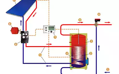
Used solar water heaters-active or passive type. In the active system uses electric pump to circulate fluid through the collector. Passive system has no pump and uses only natural circulation. The active heating more efficient, but more expensive to operate. The active circulation system is used to produce hot water in absorption (adsorption) refrigeration machines (heat pumps), villas, cottages or in the office premises. The passive system is the most widely used for heating water in domestic use in apartment buildings without the high buildings. The system is simple, reliable and not expensive.
Solar energy is used to heat air which is pumped through air ducts. Often, air ducts for air heating integrated in building designs of buildings.
The efficiency and reliability of solar collectors for water heating have been greatly improved with the use of heat pipes. Studies have shown that their thermal performance in passive heating systems is comparable with equivalent indicators of active systems. Heat pipes (TT) or closed two-phase thermosyphons (TPA) also provide adequate protection from freezing at temperatures below 0°C.
Solar collectors with heat pipes or two-phase thermosyphons have design similar instrumentation. Teplovosprinimajushchimi panel is made of the sections of the evaporation zone of the heat pipes. Parts of the zone of condensation of heat pipes in all structures placed in the accumulator tank. The differences are in the design of the ribs or fins in the areas of the zones of evaporation and configuration of channels for the passage of water or air. Some structural differences at sites of condensation zones of heat pipes, which are placed in the accumulator tank, e.g. a longitudinal or helical ribs.
In U.S. patent proposed a heat collector, teplovosprinimajushchimi panel which has channels filled with coolant. When heated fluid evaporates, vapors rise in the annular channel, which is placed in the tank to heat the water. This method of heat transfer applies to the operation principle of the heat pipe. Construction of the collector provides a high degree of heat transfer and a large enough performance. The design of the collector the method of heat transfer has a number of disadvantages. The design is not manufacturable from the viewpoint of manufacture, it is difficult to make charging the coolant channels. Uneven and not good enough hot water in the tank.
Solar collectors for water heating, for example, companies “Globe Solar Energy” Inc. (Canada), “ECOTEC” (Israel) and other companies contain a heat pipe. Parts of the zone of evaporation heat pipes placed in a glass shell, and parts of the zone of condensation located in the accumulator tank or in a tubular manifold. In glass shells supported the set vacuum (10 to 30 PSA). The vacuum level depends on the area of absorption of the collector. Despite solid advertising, collectors glass vacuum shells are not in great demand among consumers. This is due to the fact that the manifold is heavy, has high cost and low reliability of the design.
There are different designs of solar collectors combined type. Collectors combined type allow to get hot water or air and electrical energy.
Combined sewers are generally performed on a standard base tube collector for heating water or flat polymer plate. On top of a tubular manifold over the entire area of absorption of solar energy photovoltaic panels are placed. This arrangement of the collector ensures the production of thermal and electric energy with more efficient use constructive area of the collector.
We have developed several designs of solar collectors combined block type. The main focus of the design of the collectors made to increase the efficiency of converting solar energy into heat. For this purpose, as heat transfer elements used in heat pipes (closed two-phase thermosyphons). As a generator of electrical energy was used by one of the numerous modifications of the photovoltaic panels with an installed capacity of about 100 watts. The figure below shows a diagram of one of the structures of the combined manifold.
And block the absorption of solar energy; In – unit water heating and electricity generation; 1 — insulated box; 2 – glass boxes; 3 – photovoltaic panel; 4 – areas of zones of evaporation heat pipes; 5 – electric heating elements; 6 – fins; 7 – teplovosprinimajushchimi panel; 8 – heat exchanger section; 9 – areas of condensation zones of heat pipes; 10 – plug connectors.
A combined manifold is formed of heat pipes and consists of the absorption of solar thermal energy, heating block and water block the generation of electric energy. The unit water heating system is designed as a heat exchanger type "pipe in pipe". The heat exchanger consists of sections, whose number can match the number of heat pipes. The developed design of the collector in which the heat exchanger contains a number of sections equal to twice the number of heat pipes. For example, the number of heat pipes is equal to 8, and the number of sections of heat exchanger 16. The transfer of heat to heated water in the heat exchanger can be realized in two ways: direct contact of the surface of the condensing zone of the heat pipe with water or the method of "dry contact". In the latter case the heat transfer is carried out in two heat-conducting walls. The developed design of a combined collector with heat pipes, on the surface of the evaporator sections which are mounted electric heating elements.
Teplovosprinimajushchimi square panel, which consists of sections of evaporation amounts to 60 to 70% of the total area of the collector. For systems with natural circulation, teplovosprinimajushchimi the surface should be larger than for systems of the active type.
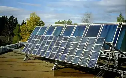
Experienced solar collector system the figures below show a prototype system solar water heaters of the active type. The system consists of 2 solar heaters, each of which is connected to the tank with a water capacity Vt=150 liters (kg). Circulation of water through the heaters is carried out by centrifugal pumps. Heaters teplovosprinimajushchimi surfaces facing South-West and set at an angle of 35 degrees to the horizon.
Check the efficiency of water heaters was carried out using a solar collector company “NIMROD” (Israel). The standard heater consists of a thermally insulated box, which contains 8 pieces teplovosprinimajushchimi copper tubes O16/14 mm, in which heated water circulates. Teplovosprinimajushchimi tubes welded to two pipes with an inner diameter of 26.5 mm. the tubes are placed fins, which are made of aluminum plates with a thickness of 0.5 mm. the Fins are covered with black paint to increase heat absorption capacity. The total heat absorbing surface of the standard panel is Fst = 2.565 m2. The area of the orifice teplovosprinimajushchimi tubes is 0.00123 m2.
To supply water in a solar heater using a centrifugal pump of the brand of the SR3-20/40. The pump has three modes of operation that provide the pump performance: 2 m3/h 2.6 m3/h 3.75 m3/h. At maximum output the flow rate of water in pipes solar heater is 0.8 m/sec.
New combined solar heater is also made on the basis of panel firm “NIMROD”. The header consists of blocks which are placed in a standard insulated box. Of 8 pieces of pipes of the specified panel has been manufactured heat pipe (in our case, the closed two-phase thermosyphons). Each DTS was filled with a binary fluid to methanol. The amount of coolant in the DTS is 150 ml. portions of the zones of evaporation fins form teplovosprinimajushchimi panel. Area teplovosprinimajushchimi panel equal to 1.67 m2. In the evaporation areas are the fins the same size as the standard heater. The length of the evaporation is on the order of 1.3 m. the Square teplovosprinimajushchimi panel combined manifold 1.4 times smaller than the standard manifold.
Condenser sections of the TPA are placed in the sections of the heat exchanger type "pipe in pipe". To increase the degree of contact between the surface of the condenser sections of DTS and the walls of the heat exchanger, into the gap was placed on the aluminum shavings. The inner surface of the heating water is about 0.393 m2. Square orifice for the water is 0.00768 m2. Considering that the area of the orifice for a water heater to heat pipes in 6.2 times more to ensure that speed 0.8 m/sec, through the heater must be pumped 6.08 m3/hour of water, i.e. almost two times more than a standard heater.
Standard photovoltaic panels installation with a nominal power of 100 W with a working surface of 1.14 m2 provides for daylight charging battery voltage 12V capacity 55-60 a·h. When the consumption current of the battery 5A·hour, the pump or the heater power of 200 W can work for 10 to 12 hours.
Methods of processing and analysis of experimental data
There are several methods for determining the effectiveness or efficiency of the solar heaters. Common methods of calculation, which was based on the principle of subtraction from the value of the ideal absorptive capacity of the collector the inevitable heat losses. Such losses include: the conversion factor of solar energy (for) and loss factors (A1, A2). The conversion factor () takes into account the optical losses of the solar collector, the coefficients A1 and A2 the heat losses of the collector.
To determine the effectiveness of converting solar energy collector in a particular area and set of external conditions the formula:
where a parameter (x) of the accepted construction of the reservoir is determined based on the average outside air temperature (tam), the average heated water temperature (twm) and the amount of solar radiation (G).
As can be seen from the dimension specifications dimension (X) represents the variable value of thermal resistance. For a given latitude and area solar radiation constant (not considering the daily changes of weather conditions such as clouds, dust, etc.). Therefore, the change in the value (X) depends on the temperature difference between the heated water and the ambient air, or rather, just from the air temperature. May be considered appropriate, relate the efficiency of the collector only to the magnitude of the solar radiation or average temperature.
Present graphics of "efficiency" in the function η=f(X) by companies manufacturers of solar collectors is the same, although the numerical values of coefficients of heat losses taken.
Of course, relative to the accepted values of coefficients of heat losses of the collector, there are significant doubts. For example, a testing laboratory in Switzerland (SPF report C63LPEN) on the basis of the surface area of absorption suggested the following set of values to calculate the efficiency of solar collectors:
— conversion ratio: = 0.717;
— loss coefficient: A1 = 1.52 W/(m2 · K);
— loss coefficient: A2 = 0.0085 W/(m2 · K);
Other laboratories and companies offer their values of loss coefficients, which, in turn, depend on many external and structural factors. For example, optical losses of the collector generally ranges from 14% to 26%, and sometimes reaching 32% and more. That is, the conversion ratio (for) taking values from 0.86 to 0.68 and below. As one might expect, the numerical values of coefficients of heat loss (A1) and (A2) taken on the basis of experimental data for a particular design and the area of the collector. The question arises whether it is legitimate to distribute the numerical values of heat losses on all the manufactured solar collector?
If the dimension of the coefficient (A1) is not in doubt, the dimension of the coefficient (A2), where the temperature is given in the square, not that other, as a mathematical technique to obtain the final dimensionless quantity. Using this mathematical technique, to avoid errors in calculations. From the point of view of the heat exchange process, the methods of calculating the efficiency of the collector can not objectively evaluate the benefits of a particular design of the manifold.
Of course, to assess the efficiency of the collectors combined type according to known methods is not possible. To determine the values for heat losses are required to conduct a large number of experiments with all the diverse changes of influencing factors. For General consumers the most important feature of a solar collector is the number and maximum temperature of the heated water during daylight hours. This provision tells what method to verify the effectiveness of a particular design of solar collector.
Therefore, the evaluation of new constructions of solar collectors was determined average value of the thermal energy absorbed in the heated water for a certain period of time light of day. The effectiveness of the new structures of the collectors was compared with the standard headers that exist in the markets of many countries.
When evaluating the efficiency of solar heaters have measured water temperature at the outlet of the tanks and the ambient air temperature. For the comparative analysis was based on the following parameters: the same capacity (capacity) tanks are the same and constant flow rate in the pipes to the standard heater and in the sections of the heat exchanger of the combined manifold. As mentioned above, a test was carried out for heating systems with an active water circulation system. Currently, these parameters are checked the system with natural circulation of water. For a system with natural circulation of water combined made the manifold with the heat pipes and installed a standard manifold. The dimensions of the manifolds are the same.
Temperature of water and air was measured every hour starting from 8.00 am to 16.00 PM. The flow velocity in the pipes to the standard heater and the coil sections of the new reservoir was maintained within 0.8 m/sec.
3 month test cycle, a few days (17.07., 21.07. and 24.07.2011 year) measurements were carried out from 8.00 am to 11.00 am. In some days of measurements of temperature of water and air was carried out till 18.00 PM. Such measurements were carried out at 1.08 3.08. 2011.
The amount of heat energy that is absorbed by the water in the solar heater, determined by the formula:
The efficiency of heat absorption or the amount of heat flux at teplovosprinimajushchimi the surface of the solar heaters have been found from the expressions:
The efficiency (η), or thermal efficiency of solar heaters was calculated as the ratio of the amount of absorbed heat P solar heaters to the magnitude of the solar radiation G for the given latitude and the season.
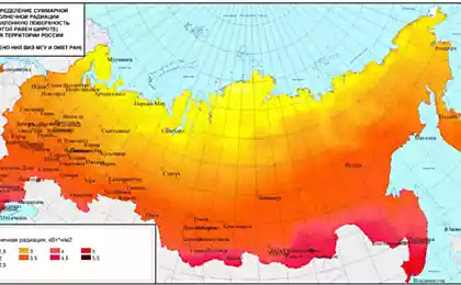
For latitude, which is Israel, the amount of solar radiation for spring and summer period may be G = 950 – 1,100 W/m2 for autumn and winter period the solar radiation is equal to G = 750 – 950 W/m2.
Results of experimental verification of the Results of check of efficiency of solar heaters are the standard type and heat pipes for different weather conditions 3-month summer period is shown in the figure below. The graph shows averaged values of the heat flow during the daylight hours when the sun's rays fell on teplovosprinimajushchimi surface reservoirs. The calculated efficiency of heat absorption (P) heaters related to the magnitude of the solar radiation is 900 W/m2. As can be seen from the graph the thermal efficiency of the combined manifold 2.0–2.36 times higher than the standard heater. It should be noted that teplovosprinimajushchimi surface of the combined collector heat pipes 40% less than a standard manifold.
The test results for the standard heater shows that the amount of heat absorbed by 1 m2 teplovosprinimajushchimi the surface, mainly depends on the duration of heating and the initial temperature difference between the water in the tank and the outside air. The amount of absorbed thermal energy for 8 hours of work and average of 16,500 kJ, and for 10 hours – 20,500 kJ. Standard manifold is very sensitive to the change of the degree of cloudiness during daylight hours. In clear weather the water heating is fast enough, especially from 9.00 am to 13.00 PM. Heater in standard hot water temperature in the summer ranges from 52.1°to 63.3°C. the Measured average temperature for the period of the test was 29 — 31°C. the Maximum achieved density while the heat amounted to P = 300 W/m2. Monthly average thermal efficiency standard manifold R = 220 W/m2 in winter and R = 243 W/m2 in summer. The average efficiency of a standard collector with an active water circulation in June amounted to 21.7%. The estimated thermal efficiency of the collector in July was 21.2%, in the month of August – 21.48 us%. These values of thermal efficiency are fully consistent with known types of standard collectors, which operate on the active water circulation system.
Testing of the combined manifold heat pipes showed a high effectiveness of the proposed design of the heater. In this collector the heat transfer from the walls of the condensing zone of the heat pipes to the heated water was carried out using "dry contact". In addition, the gap between the wall of the heat pipe and the wall section of the heat exchanger to improve the contact placed the aluminum foil.
In the summer months, heating the water in the collector heat pipe was more intense. Initial water temperature in the tanks of the standard manifold and manifold combo is the same. As a rule, the intensity of heat in the collector heat pipes were 3.8 – 4.6°C higher than the standard manifold. In the month of August indicated the intensity of heat reached 5.2 – 7.4°C. the Amount of absorbed energy in the collector averaged: over 8 hours 20,600 kJ, 10 hours work is 25,000 kJ. The greater the amount of absorbed thermal energy collector with heat pipes can be explained by the fact that the heat pipes have the storage capacity. The average temperature of hot water in the winter months was 56.0 C to 60.6°C, and in summer months, heating the water reached 59.2 – 72.0°C. the Thermal efficiency of the collector amounted to P = 510 W/m2 in summer and R = 550 W/m2 during the winter months. The efficiency factor collector heat pipes is in the range of 42-50%.
Thermal efficiency and heat absorption efficiency of collector with heat pipes are shown in the figures below.
Graphs relate to the period testing of the combined manifold from mid December 2010 to mid March 2011. All measured and calculated data were averaged by weekly periods. To calculate the thermal efficiency in the winter and spring period (March month) the amount of solar radiation was taken to be equal to 750 W/m2 in summer – equal to 950 W/m2. As follows from the results of the tests in the winter combined collector shows higher efficiency. This is because the heat pipes have the storage ability, and thereby provide a longer period to heat the water. In winter, the duration of measurements was also carried out for 8 hours a day time.
It should be noted that standard solar collectors is also used to ensure the operation of the absorption (Company “SK SonnenKlima” GmbH) or adsorption (Company “SolarTech” AG) heat pumps. With the power of chillers (7-8) kW required to install solar collectors with a total capacity (13-14) kW. To obtain such a thermal power set 6-8 units of solar collectors the standard type with teplovosprinimajushchimi surface (2.6–2.8) m2. To achieve the same (13-14) kW of thermal energy in combined sewers for heat pipes is required to install 3-4 units collectors. Overall dimensions of combined collectors is the same as the standard collectors. When this combined solar collectors allow to obtain electrical energy, which is enough to drive circulation pumps.
The results of the tests of solar collectors
— Thermal efficiency of the collector with heat pipes and a heat exchanger type "pipe in pipe" even when the method of heat transfer by the method of "dry contact" above 55-65% in comparison with solar collectors of conventional type;
— The presence of photovoltaic panels allows you to extend the working range of the collector, as in the night time and at low value of solar radiation (cloudy or rainy weather);
— Use heat pipes of binary coolants with low boiling points ensures quick start-up of the manifold into work and reduces heat loss, and in the absence of solar radiation, the heat discharge into the environment is minimal;
— The presence of electric heating elements in areas of evaporation heat pipes to provide hot water during the day for 12-15 hours;
— Simple design combined manifold allows the manufacture of collectors with a low cost and sell at competitive prices.
List of symbols cw – heat capacity of water, kJ/(kg K);
F – teplovosprinimajushchimi surface area, m2;
G – solar radiation in W/m2;
M – the number of the heated water, kg;
Q – quantity of heat absorbed by the heater, kJ;
P – the thermal efficiency of the heater in W/m2;
V – tank capacity, liters
t – temperature, °C; Greek:
τ – duration of operation of the heaters, h;
η – the efficiency of the heater; Index:
aa – average temperature;
awhp = average temperature of the water in the tank collector with heat pipes;
awst – average water temperature in the tank is a standard header;
hp – collector with heat pipes;
st – standard manifold;
w – option water.
Source: alternativenergy.ru
Solar collectors and water heaters represent heat exchangers made in the form of a conventional tubular radiators. The number of tubes of the radiator is 4, 6, 8 pieces, which are welded to the two tubes. Water enters the tubes of the radiator through one of the tubes and through the other flows in the collection or system. Tubular radiator is placed in a thermally insulated box, which one side is closed with glass. Due to the absorption of solar thermal energy water which circulates in tubes heated. To increase the area of absorption of heat tube provide aluminum fins. Absorptive capacity increase, covering fins with black paint.

Used solar water heaters-active or passive type. In the active system uses electric pump to circulate fluid through the collector. Passive system has no pump and uses only natural circulation. The active heating more efficient, but more expensive to operate. The active circulation system is used to produce hot water in absorption (adsorption) refrigeration machines (heat pumps), villas, cottages or in the office premises. The passive system is the most widely used for heating water in domestic use in apartment buildings without the high buildings. The system is simple, reliable and not expensive.
Solar energy is used to heat air which is pumped through air ducts. Often, air ducts for air heating integrated in building designs of buildings.
The efficiency and reliability of solar collectors for water heating have been greatly improved with the use of heat pipes. Studies have shown that their thermal performance in passive heating systems is comparable with equivalent indicators of active systems. Heat pipes (TT) or closed two-phase thermosyphons (TPA) also provide adequate protection from freezing at temperatures below 0°C.
Solar collectors with heat pipes or two-phase thermosyphons have design similar instrumentation. Teplovosprinimajushchimi panel is made of the sections of the evaporation zone of the heat pipes. Parts of the zone of condensation of heat pipes in all structures placed in the accumulator tank. The differences are in the design of the ribs or fins in the areas of the zones of evaporation and configuration of channels for the passage of water or air. Some structural differences at sites of condensation zones of heat pipes, which are placed in the accumulator tank, e.g. a longitudinal or helical ribs.
In U.S. patent proposed a heat collector, teplovosprinimajushchimi panel which has channels filled with coolant. When heated fluid evaporates, vapors rise in the annular channel, which is placed in the tank to heat the water. This method of heat transfer applies to the operation principle of the heat pipe. Construction of the collector provides a high degree of heat transfer and a large enough performance. The design of the collector the method of heat transfer has a number of disadvantages. The design is not manufacturable from the viewpoint of manufacture, it is difficult to make charging the coolant channels. Uneven and not good enough hot water in the tank.
Solar collectors for water heating, for example, companies “Globe Solar Energy” Inc. (Canada), “ECOTEC” (Israel) and other companies contain a heat pipe. Parts of the zone of evaporation heat pipes placed in a glass shell, and parts of the zone of condensation located in the accumulator tank or in a tubular manifold. In glass shells supported the set vacuum (10 to 30 PSA). The vacuum level depends on the area of absorption of the collector. Despite solid advertising, collectors glass vacuum shells are not in great demand among consumers. This is due to the fact that the manifold is heavy, has high cost and low reliability of the design.
There are different designs of solar collectors combined type. Collectors combined type allow to get hot water or air and electrical energy.
Combined sewers are generally performed on a standard base tube collector for heating water or flat polymer plate. On top of a tubular manifold over the entire area of absorption of solar energy photovoltaic panels are placed. This arrangement of the collector ensures the production of thermal and electric energy with more efficient use constructive area of the collector.
We have developed several designs of solar collectors combined block type. The main focus of the design of the collectors made to increase the efficiency of converting solar energy into heat. For this purpose, as heat transfer elements used in heat pipes (closed two-phase thermosyphons). As a generator of electrical energy was used by one of the numerous modifications of the photovoltaic panels with an installed capacity of about 100 watts. The figure below shows a diagram of one of the structures of the combined manifold.
And block the absorption of solar energy; In – unit water heating and electricity generation; 1 — insulated box; 2 – glass boxes; 3 – photovoltaic panel; 4 – areas of zones of evaporation heat pipes; 5 – electric heating elements; 6 – fins; 7 – teplovosprinimajushchimi panel; 8 – heat exchanger section; 9 – areas of condensation zones of heat pipes; 10 – plug connectors.
A combined manifold is formed of heat pipes and consists of the absorption of solar thermal energy, heating block and water block the generation of electric energy. The unit water heating system is designed as a heat exchanger type "pipe in pipe". The heat exchanger consists of sections, whose number can match the number of heat pipes. The developed design of the collector in which the heat exchanger contains a number of sections equal to twice the number of heat pipes. For example, the number of heat pipes is equal to 8, and the number of sections of heat exchanger 16. The transfer of heat to heated water in the heat exchanger can be realized in two ways: direct contact of the surface of the condensing zone of the heat pipe with water or the method of "dry contact". In the latter case the heat transfer is carried out in two heat-conducting walls. The developed design of a combined collector with heat pipes, on the surface of the evaporator sections which are mounted electric heating elements.
Teplovosprinimajushchimi square panel, which consists of sections of evaporation amounts to 60 to 70% of the total area of the collector. For systems with natural circulation, teplovosprinimajushchimi the surface should be larger than for systems of the active type.
Experienced solar collector system the figures below show a prototype system solar water heaters of the active type. The system consists of 2 solar heaters, each of which is connected to the tank with a water capacity Vt=150 liters (kg). Circulation of water through the heaters is carried out by centrifugal pumps. Heaters teplovosprinimajushchimi surfaces facing South-West and set at an angle of 35 degrees to the horizon.
Check the efficiency of water heaters was carried out using a solar collector company “NIMROD” (Israel). The standard heater consists of a thermally insulated box, which contains 8 pieces teplovosprinimajushchimi copper tubes O16/14 mm, in which heated water circulates. Teplovosprinimajushchimi tubes welded to two pipes with an inner diameter of 26.5 mm. the tubes are placed fins, which are made of aluminum plates with a thickness of 0.5 mm. the Fins are covered with black paint to increase heat absorption capacity. The total heat absorbing surface of the standard panel is Fst = 2.565 m2. The area of the orifice teplovosprinimajushchimi tubes is 0.00123 m2.
To supply water in a solar heater using a centrifugal pump of the brand of the SR3-20/40. The pump has three modes of operation that provide the pump performance: 2 m3/h 2.6 m3/h 3.75 m3/h. At maximum output the flow rate of water in pipes solar heater is 0.8 m/sec.
New combined solar heater is also made on the basis of panel firm “NIMROD”. The header consists of blocks which are placed in a standard insulated box. Of 8 pieces of pipes of the specified panel has been manufactured heat pipe (in our case, the closed two-phase thermosyphons). Each DTS was filled with a binary fluid to methanol. The amount of coolant in the DTS is 150 ml. portions of the zones of evaporation fins form teplovosprinimajushchimi panel. Area teplovosprinimajushchimi panel equal to 1.67 m2. In the evaporation areas are the fins the same size as the standard heater. The length of the evaporation is on the order of 1.3 m. the Square teplovosprinimajushchimi panel combined manifold 1.4 times smaller than the standard manifold.
Condenser sections of the TPA are placed in the sections of the heat exchanger type "pipe in pipe". To increase the degree of contact between the surface of the condenser sections of DTS and the walls of the heat exchanger, into the gap was placed on the aluminum shavings. The inner surface of the heating water is about 0.393 m2. Square orifice for the water is 0.00768 m2. Considering that the area of the orifice for a water heater to heat pipes in 6.2 times more to ensure that speed 0.8 m/sec, through the heater must be pumped 6.08 m3/hour of water, i.e. almost two times more than a standard heater.
Standard photovoltaic panels installation with a nominal power of 100 W with a working surface of 1.14 m2 provides for daylight charging battery voltage 12V capacity 55-60 a·h. When the consumption current of the battery 5A·hour, the pump or the heater power of 200 W can work for 10 to 12 hours.
Methods of processing and analysis of experimental data
There are several methods for determining the effectiveness or efficiency of the solar heaters. Common methods of calculation, which was based on the principle of subtraction from the value of the ideal absorptive capacity of the collector the inevitable heat losses. Such losses include: the conversion factor of solar energy (for) and loss factors (A1, A2). The conversion factor () takes into account the optical losses of the solar collector, the coefficients A1 and A2 the heat losses of the collector.
To determine the effectiveness of converting solar energy collector in a particular area and set of external conditions the formula:
where a parameter (x) of the accepted construction of the reservoir is determined based on the average outside air temperature (tam), the average heated water temperature (twm) and the amount of solar radiation (G).
As can be seen from the dimension specifications dimension (X) represents the variable value of thermal resistance. For a given latitude and area solar radiation constant (not considering the daily changes of weather conditions such as clouds, dust, etc.). Therefore, the change in the value (X) depends on the temperature difference between the heated water and the ambient air, or rather, just from the air temperature. May be considered appropriate, relate the efficiency of the collector only to the magnitude of the solar radiation or average temperature.
Present graphics of "efficiency" in the function η=f(X) by companies manufacturers of solar collectors is the same, although the numerical values of coefficients of heat losses taken.
Of course, relative to the accepted values of coefficients of heat losses of the collector, there are significant doubts. For example, a testing laboratory in Switzerland (SPF report C63LPEN) on the basis of the surface area of absorption suggested the following set of values to calculate the efficiency of solar collectors:
— conversion ratio: = 0.717;
— loss coefficient: A1 = 1.52 W/(m2 · K);
— loss coefficient: A2 = 0.0085 W/(m2 · K);
Other laboratories and companies offer their values of loss coefficients, which, in turn, depend on many external and structural factors. For example, optical losses of the collector generally ranges from 14% to 26%, and sometimes reaching 32% and more. That is, the conversion ratio (for) taking values from 0.86 to 0.68 and below. As one might expect, the numerical values of coefficients of heat loss (A1) and (A2) taken on the basis of experimental data for a particular design and the area of the collector. The question arises whether it is legitimate to distribute the numerical values of heat losses on all the manufactured solar collector?
If the dimension of the coefficient (A1) is not in doubt, the dimension of the coefficient (A2), where the temperature is given in the square, not that other, as a mathematical technique to obtain the final dimensionless quantity. Using this mathematical technique, to avoid errors in calculations. From the point of view of the heat exchange process, the methods of calculating the efficiency of the collector can not objectively evaluate the benefits of a particular design of the manifold.
Of course, to assess the efficiency of the collectors combined type according to known methods is not possible. To determine the values for heat losses are required to conduct a large number of experiments with all the diverse changes of influencing factors. For General consumers the most important feature of a solar collector is the number and maximum temperature of the heated water during daylight hours. This provision tells what method to verify the effectiveness of a particular design of solar collector.
Therefore, the evaluation of new constructions of solar collectors was determined average value of the thermal energy absorbed in the heated water for a certain period of time light of day. The effectiveness of the new structures of the collectors was compared with the standard headers that exist in the markets of many countries.
When evaluating the efficiency of solar heaters have measured water temperature at the outlet of the tanks and the ambient air temperature. For the comparative analysis was based on the following parameters: the same capacity (capacity) tanks are the same and constant flow rate in the pipes to the standard heater and in the sections of the heat exchanger of the combined manifold. As mentioned above, a test was carried out for heating systems with an active water circulation system. Currently, these parameters are checked the system with natural circulation of water. For a system with natural circulation of water combined made the manifold with the heat pipes and installed a standard manifold. The dimensions of the manifolds are the same.
Temperature of water and air was measured every hour starting from 8.00 am to 16.00 PM. The flow velocity in the pipes to the standard heater and the coil sections of the new reservoir was maintained within 0.8 m/sec.
3 month test cycle, a few days (17.07., 21.07. and 24.07.2011 year) measurements were carried out from 8.00 am to 11.00 am. In some days of measurements of temperature of water and air was carried out till 18.00 PM. Such measurements were carried out at 1.08 3.08. 2011.
The amount of heat energy that is absorbed by the water in the solar heater, determined by the formula:
The efficiency of heat absorption or the amount of heat flux at teplovosprinimajushchimi the surface of the solar heaters have been found from the expressions:
The efficiency (η), or thermal efficiency of solar heaters was calculated as the ratio of the amount of absorbed heat P solar heaters to the magnitude of the solar radiation G for the given latitude and the season.
For latitude, which is Israel, the amount of solar radiation for spring and summer period may be G = 950 – 1,100 W/m2 for autumn and winter period the solar radiation is equal to G = 750 – 950 W/m2.
Results of experimental verification of the Results of check of efficiency of solar heaters are the standard type and heat pipes for different weather conditions 3-month summer period is shown in the figure below. The graph shows averaged values of the heat flow during the daylight hours when the sun's rays fell on teplovosprinimajushchimi surface reservoirs. The calculated efficiency of heat absorption (P) heaters related to the magnitude of the solar radiation is 900 W/m2. As can be seen from the graph the thermal efficiency of the combined manifold 2.0–2.36 times higher than the standard heater. It should be noted that teplovosprinimajushchimi surface of the combined collector heat pipes 40% less than a standard manifold.
The test results for the standard heater shows that the amount of heat absorbed by 1 m2 teplovosprinimajushchimi the surface, mainly depends on the duration of heating and the initial temperature difference between the water in the tank and the outside air. The amount of absorbed thermal energy for 8 hours of work and average of 16,500 kJ, and for 10 hours – 20,500 kJ. Standard manifold is very sensitive to the change of the degree of cloudiness during daylight hours. In clear weather the water heating is fast enough, especially from 9.00 am to 13.00 PM. Heater in standard hot water temperature in the summer ranges from 52.1°to 63.3°C. the Measured average temperature for the period of the test was 29 — 31°C. the Maximum achieved density while the heat amounted to P = 300 W/m2. Monthly average thermal efficiency standard manifold R = 220 W/m2 in winter and R = 243 W/m2 in summer. The average efficiency of a standard collector with an active water circulation in June amounted to 21.7%. The estimated thermal efficiency of the collector in July was 21.2%, in the month of August – 21.48 us%. These values of thermal efficiency are fully consistent with known types of standard collectors, which operate on the active water circulation system.
Testing of the combined manifold heat pipes showed a high effectiveness of the proposed design of the heater. In this collector the heat transfer from the walls of the condensing zone of the heat pipes to the heated water was carried out using "dry contact". In addition, the gap between the wall of the heat pipe and the wall section of the heat exchanger to improve the contact placed the aluminum foil.
In the summer months, heating the water in the collector heat pipe was more intense. Initial water temperature in the tanks of the standard manifold and manifold combo is the same. As a rule, the intensity of heat in the collector heat pipes were 3.8 – 4.6°C higher than the standard manifold. In the month of August indicated the intensity of heat reached 5.2 – 7.4°C. the Amount of absorbed energy in the collector averaged: over 8 hours 20,600 kJ, 10 hours work is 25,000 kJ. The greater the amount of absorbed thermal energy collector with heat pipes can be explained by the fact that the heat pipes have the storage capacity. The average temperature of hot water in the winter months was 56.0 C to 60.6°C, and in summer months, heating the water reached 59.2 – 72.0°C. the Thermal efficiency of the collector amounted to P = 510 W/m2 in summer and R = 550 W/m2 during the winter months. The efficiency factor collector heat pipes is in the range of 42-50%.
Thermal efficiency and heat absorption efficiency of collector with heat pipes are shown in the figures below.
Graphs relate to the period testing of the combined manifold from mid December 2010 to mid March 2011. All measured and calculated data were averaged by weekly periods. To calculate the thermal efficiency in the winter and spring period (March month) the amount of solar radiation was taken to be equal to 750 W/m2 in summer – equal to 950 W/m2. As follows from the results of the tests in the winter combined collector shows higher efficiency. This is because the heat pipes have the storage ability, and thereby provide a longer period to heat the water. In winter, the duration of measurements was also carried out for 8 hours a day time.
It should be noted that standard solar collectors is also used to ensure the operation of the absorption (Company “SK SonnenKlima” GmbH) or adsorption (Company “SolarTech” AG) heat pumps. With the power of chillers (7-8) kW required to install solar collectors with a total capacity (13-14) kW. To obtain such a thermal power set 6-8 units of solar collectors the standard type with teplovosprinimajushchimi surface (2.6–2.8) m2. To achieve the same (13-14) kW of thermal energy in combined sewers for heat pipes is required to install 3-4 units collectors. Overall dimensions of combined collectors is the same as the standard collectors. When this combined solar collectors allow to obtain electrical energy, which is enough to drive circulation pumps.
The results of the tests of solar collectors
— Thermal efficiency of the collector with heat pipes and a heat exchanger type "pipe in pipe" even when the method of heat transfer by the method of "dry contact" above 55-65% in comparison with solar collectors of conventional type;
— The presence of photovoltaic panels allows you to extend the working range of the collector, as in the night time and at low value of solar radiation (cloudy or rainy weather);
— Use heat pipes of binary coolants with low boiling points ensures quick start-up of the manifold into work and reduces heat loss, and in the absence of solar radiation, the heat discharge into the environment is minimal;
— The presence of electric heating elements in areas of evaporation heat pipes to provide hot water during the day for 12-15 hours;
— Simple design combined manifold allows the manufacture of collectors with a low cost and sell at competitive prices.
List of symbols cw – heat capacity of water, kJ/(kg K);
F – teplovosprinimajushchimi surface area, m2;
G – solar radiation in W/m2;
M – the number of the heated water, kg;
Q – quantity of heat absorbed by the heater, kJ;
P – the thermal efficiency of the heater in W/m2;
V – tank capacity, liters
t – temperature, °C; Greek:
τ – duration of operation of the heaters, h;
η – the efficiency of the heater; Index:
aa – average temperature;
awhp = average temperature of the water in the tank collector with heat pipes;
awst – average water temperature in the tank is a standard header;
hp – collector with heat pipes;
st – standard manifold;
w – option water.
Source: alternativenergy.ru


Developed the first wireless charging for electric vehicles
Microscopic ecosystem, which we're not aware of