406
My little relay: Automatic watering is magic
Today we are going to program SDEPROM system controller for automated irrigation for a garden.
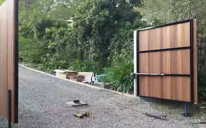
This:
Borehole with pump, pipe system with solenoid valves and sprinkler heads installed in ten different areas of the garden.
Required:
To ensure consistent start watering each zone for a predetermined period of time from 5 to 30 minutes. The sequence is required due to the fact that the well could not provide the necessary pressure at two zones. To provide the possibility of applying external control unit in order to have the ability to turn on timer to take into account soil moisture, etc.
The tackle you will find megabytes of meat, and process the slowest of the controller firmware. This is not Plesio on bitbang programming!
It all started one morning, the phone rang, and the next evening in the garage was almost half-tons of "new" Soviet relux in family boxes I've saved from landfill. Unnecessary dismantled, something went into other hands. With the remaining couple of hundred pounds it was necessary to do something :)
This project on some of the shelves of my closets. The only thing I had to buy 15 meters of thin stranded wire, and that most of the connections went 6 sets of wires from the computer PSU. The whole project took about a month. The active phase assemblies — three days.
First, take inventory of Reloj and decide what we will use:
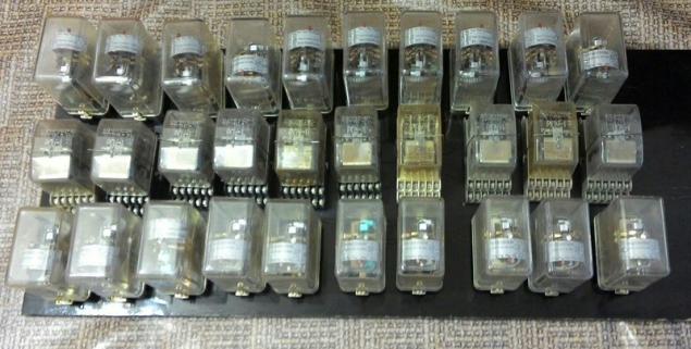
We have a 10-channel system, we assume that one relay will be responsible for enabling the channel, and another one for disconnection, and the third implement a variety of blocking and control.
The first two relays — relay maximum and minimum voltage PH-53 PH-54, for different nominal voltage operation — that was it. These relays have one normally open and one normally closed contact. You need to meet.
The third relay RPU-1. 6 BUT and 2 NC contacts. Should be enough.
A number of these relays delayed for overall control.
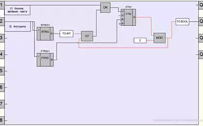
Make the night an outline of:
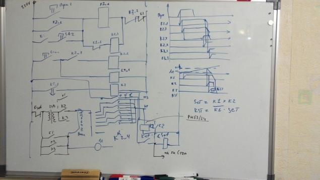
According to the principle of priority of the block next channel previous, ensuring consistency. ie while 1 channel is not finished, channel 2 will not start. Do not forget to include a sequential lock, so omitting one of the channels as not to disrupt this logic.
Time setting is determined by selecting one of the channels of programmable timer.
Since I have the switch on 7, use 7 reels time relay, single barrel we will go to the defense at the time, cutting down the channel at a time is more than the maximum. You never know, the switch is acting up. another drum go to start blocking the next channel until the reset relay time — about a second to the drum is returned to the initial starting point.
Remote
The task of the panel is to allow you to run any channel, start the desired channels for sequential execution, reset the current channel reset the entire system. To have external control.
The panel will collect in the housing of the relay D-3M protective automatic, after taking out the guts — although there are relays that we need to multiply the signals, they have too large dimensions and a new filling will not fit.
Installed buttons and switches
And mounted inside:
Relay needed for the button start. If the channel is selected using a toggle switch, pressing the total button will start the channel. Relay was DC at 110V, so installed two in series and fed through a diode bridge. Don't remember where I got them. Connectors 14 contacts took out voltmeter — recorder N392. Sense from the last few, but the accessories and the case is very useful even. Some of them were taken and tumblers.
Pinout:
1 — 10 — run channels
11 — external control channels, the circuit for 220V line to include the locking and timing circuit.
12 light stop.
13 — 220 — neutral (right in the diagrams)
14 — 220V — line (left in the diagrams)
The control unit is ready. Top-mounted type connector mother, the same Pinout on the bottom. It is possible to connect an external unit.
The LEDs are not connected — I did not use the relevant device, so just for beauty.
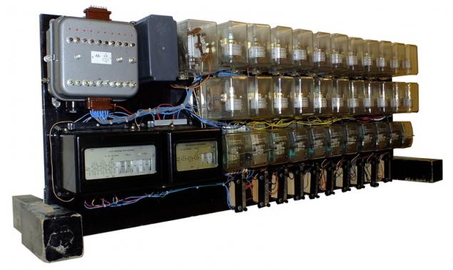
Controller
Anecdote. Was I on the porch. Look — the piano stands. Well I took it out and took it. Musicians to watch
In fact, the lower panel with its size are well suited as the basis for a future controller. The legs, incidentally, is also useful during Assembly they are securely held the entire structure in a vertical position.
Since my PH-53 rear connection, do the cuts, so then it was convenient to do the installation:
Set all relay rear connections and control panel:
And stitched the logic of inclusion:
First start — everything works, except one relay in the remote — hums but not working. stuck from long storage. A blow to the remote and everything worked as it should. Reset, disable, and fill in the free space.
While mounted the third row relays have noticed a bug in the schema. Fixed the bug in three hours the night I went to bed.
On the morning fixed bug fix...

The moment where the Pandora lies flat and sticking out from under her, my legs in picture not included. Which is a pity.
Mounted switches. They screw on 7 of relay RT-81. Since they are metal open-type, connect this circuit through the transformer to 24V so it was safe to grab with your bare hands. In the diagram above it, in a fit of night illumination, painted black. As this transformer is applied to the base unit relay РФ8300. There are inbuilt relay 24V.
Plug-in leftovers, set the time relay and custom their setting.
Run again, change the tube and remove a couple of bugs. Works!
The end result is a Programmable logic controller with the following features:
Now the controller is not enough indication of channel operation led installed, but I considered them non-Canon and while the plug did not. An indication, flag relay, but they are latching, i.e. not suitable for this case.
Still missing controller terminal block to connect solenoid valves. I will add later when I finish to design a cable line to them.
At the moment, in testing found a couple of bugs that I'll fix it and gathering expansion module for the daily set point and humidity, so he gave the signal enable at a certain time of the day if not the soil is not wet, next year will enter into operation. Honestly, I'm in the garden, even the pipes are still not laid for irrigation. published by P. S. And remember, only by changing their consumption - together we change the world! ©
Source: geektimes.ru/post/255602/

This:
Borehole with pump, pipe system with solenoid valves and sprinkler heads installed in ten different areas of the garden.
Required:
To ensure consistent start watering each zone for a predetermined period of time from 5 to 30 minutes. The sequence is required due to the fact that the well could not provide the necessary pressure at two zones. To provide the possibility of applying external control unit in order to have the ability to turn on timer to take into account soil moisture, etc.
The tackle you will find megabytes of meat, and process the slowest of the controller firmware. This is not Plesio on bitbang programming!
It all started one morning, the phone rang, and the next evening in the garage was almost half-tons of "new" Soviet relux in family boxes I've saved from landfill. Unnecessary dismantled, something went into other hands. With the remaining couple of hundred pounds it was necessary to do something :)
This project on some of the shelves of my closets. The only thing I had to buy 15 meters of thin stranded wire, and that most of the connections went 6 sets of wires from the computer PSU. The whole project took about a month. The active phase assemblies — three days.
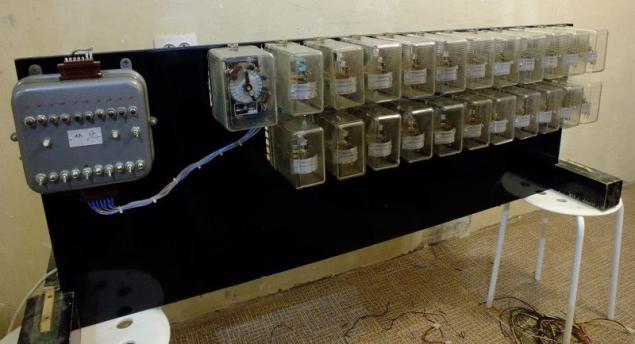
First, take inventory of Reloj and decide what we will use:

We have a 10-channel system, we assume that one relay will be responsible for enabling the channel, and another one for disconnection, and the third implement a variety of blocking and control.
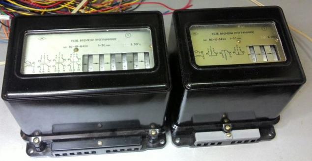
The first two relays — relay maximum and minimum voltage PH-53 PH-54, for different nominal voltage operation — that was it. These relays have one normally open and one normally closed contact. You need to meet.
The third relay RPU-1. 6 BUT and 2 NC contacts. Should be enough.
A number of these relays delayed for overall control.
Make the night an outline of:

According to the principle of priority of the block next channel previous, ensuring consistency. ie while 1 channel is not finished, channel 2 will not start. Do not forget to include a sequential lock, so omitting one of the channels as not to disrupt this logic.
Time setting is determined by selecting one of the channels of programmable timer.

Since I have the switch on 7, use 7 reels time relay, single barrel we will go to the defense at the time, cutting down the channel at a time is more than the maximum. You never know, the switch is acting up. another drum go to start blocking the next channel until the reset relay time — about a second to the drum is returned to the initial starting point.
Remote
The task of the panel is to allow you to run any channel, start the desired channels for sequential execution, reset the current channel reset the entire system. To have external control.
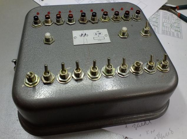
The panel will collect in the housing of the relay D-3M protective automatic, after taking out the guts — although there are relays that we need to multiply the signals, they have too large dimensions and a new filling will not fit.
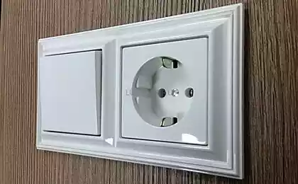
Installed buttons and switches

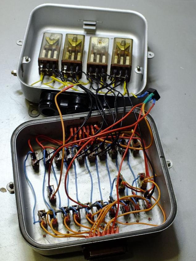
And mounted inside:

Relay needed for the button start. If the channel is selected using a toggle switch, pressing the total button will start the channel. Relay was DC at 110V, so installed two in series and fed through a diode bridge. Don't remember where I got them. Connectors 14 contacts took out voltmeter — recorder N392. Sense from the last few, but the accessories and the case is very useful even. Some of them were taken and tumblers.
Pinout:
1 — 10 — run channels
11 — external control channels, the circuit for 220V line to include the locking and timing circuit.
12 light stop.
13 — 220 — neutral (right in the diagrams)
14 — 220V — line (left in the diagrams)
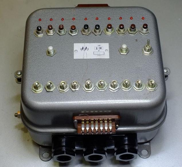
The control unit is ready. Top-mounted type connector mother, the same Pinout on the bottom. It is possible to connect an external unit.

The LEDs are not connected — I did not use the relevant device, so just for beauty.
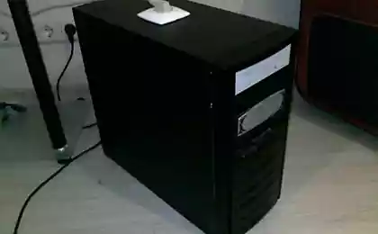
Controller
Anecdote. Was I on the porch. Look — the piano stands. Well I took it out and took it. Musicians to watch
In fact, the lower panel with its size are well suited as the basis for a future controller. The legs, incidentally, is also useful during Assembly they are securely held the entire structure in a vertical position.
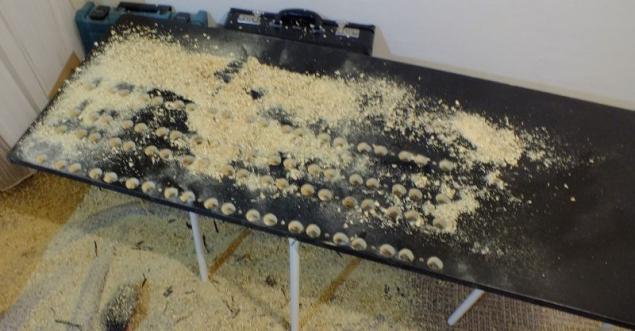
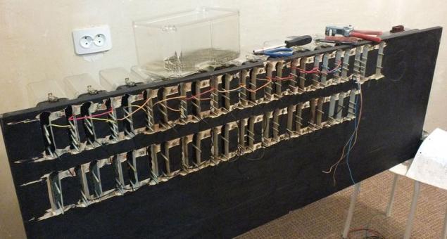
Since my PH-53 rear connection, do the cuts, so then it was convenient to do the installation:

Set all relay rear connections and control panel:

And stitched the logic of inclusion:

First start — everything works, except one relay in the remote — hums but not working. stuck from long storage. A blow to the remote and everything worked as it should. Reset, disable, and fill in the free space.
While mounted the third row relays have noticed a bug in the schema. Fixed the bug in three hours the night I went to bed.
On the morning fixed bug fix...

The moment where the Pandora lies flat and sticking out from under her, my legs in picture not included. Which is a pity.
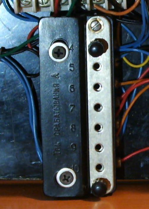
Mounted switches. They screw on 7 of relay RT-81. Since they are metal open-type, connect this circuit through the transformer to 24V so it was safe to grab with your bare hands. In the diagram above it, in a fit of night illumination, painted black. As this transformer is applied to the base unit relay РФ8300. There are inbuilt relay 24V.

Plug-in leftovers, set the time relay and custom their setting.

Run again, change the tube and remove a couple of bugs. Works!
The end result is a Programmable logic controller with the following features:
- The number of logical cells — 33
- Type programmable memory SDEPROM (ScrewDriver Erasable Programmable Read-Only Memory)
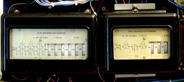
- Two timer from 1 to 30 minutes — one 6 channel and one 3 channel
- One timer from 1 to 21 seconds on 2 channels.
- The maximum speed of programming — 20 jumpers/hour.
- The average speed of programming — 6 jumpers/hour
- The size of the controller 1333х500х200мм
- Weight controller — 45 kg
Now the controller is not enough indication of channel operation led installed, but I considered them non-Canon and while the plug did not. An indication, flag relay, but they are latching, i.e. not suitable for this case.
Still missing controller terminal block to connect solenoid valves. I will add later when I finish to design a cable line to them.
At the moment, in testing found a couple of bugs that I'll fix it and gathering expansion module for the daily set point and humidity, so he gave the signal enable at a certain time of the day if not the soil is not wet, next year will enter into operation. Honestly, I'm in the garden, even the pipes are still not laid for irrigation. published by P. S. And remember, only by changing their consumption - together we change the world! ©
Source: geektimes.ru/post/255602/