607
Personal hydrogen storage
Many of us (especially the residents) would like to have their own personal generator and to be independent from the existing utility structures. It would be cool to put in the yard the wind turbine or make the roof of his house from solar panels and even not to let the wiring.
And it seems modern technology could provide decent device elektrogeneratory (modern solar panels already have an acceptable efficiency and life, to the wind turbines is also critical of the comments there), but the system of accumulation and storage of electricity, are most of batteries have some significant drawbacks (high cost, low capacity, short life, poor performance characteristics at low temperatures, etc.). And these disadvantages make the whole concept of individual, renewable electricity, unattractive to ordinary citizens.
In this article I propose to explore the concept of individual hydrogen storage of electricity, which, in a certain perspective, can replace the classic batteries.
NotesAll the images are purely conceptual in nature, the design of the engineering model will necessarily have to review all the sizes and features of the device components; I assume that somewhere described analog device, it is even possible there are commercial samples, but I didn't find anything similar. The General concept (principle of operation)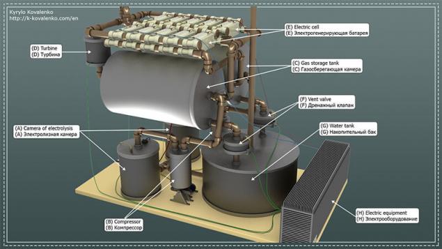
Despite the fact that the design was very cumbersome, the principle of operation is quite simple. Coming from a renewable source (solar panel, windmill, etc.) the electric current is fed into two electrolysis chambers (A), where the result of the electrolysis process begins to accumulate oxygen/hydrogen.
The resulting oxygen/hydrogen with a compressor (B) is pumped into the gas-storage chamber ©. From the gas-storage chamber ©, oxygen/hydrogen is supplied to the power generating battery (E), and then not participating in the reaction of oxygen/hydrogen, and the resulting reaction water is returned to the gas-storage chamber. The resulting chemical Union of oxygen and hydrogen, the electric current supplied to the transformer, then to the inverter and the control unit of the turbine/drain valve (H). With inverter, electric current is supplied to the consumer.
Accumulated in the gas-storage chamber water through the drainage mechanism (F) is transferred to the storage tank (G) and back to the electrolysis chamber.
Next, I suggest a closer look at the mechanics of operation of the system components.
The electrolysis chamber isthe Main purpose — the development and initial accumulation of oxygen/hydrogen, and passes to the compressor.
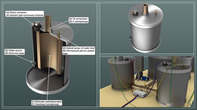
Coming into contact (A) electric current enters the electrode © where he begins the process of electrolysis of water in the chamber. Gas gradually accumulate in the top of the camera and getting directly to the compressor through the hole (E), pushes water through the opening (B) back into the tank. Thus there is a primary accumulation of gas before injection into the gas-storage chamber of the compressor. The whole process of primary accumulation of gas is controlled by optical (laser) sensor (D), the readings of which are transmitted to the control device.
Compressor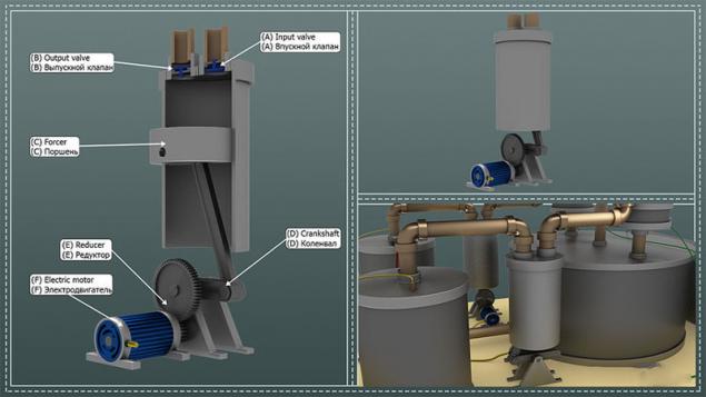
The main purpose of the pump is obtained in the electrolysis of the gas in the gas-storage chamber.
Gas (oxygen/hydrogen) from the electrolysis chamber into the chamber of the compressor through the valve (A). When the gas in the chamber of the compressor is accumulated in sufficient quantity (the signal comes from the optical sensor electrolysis chamber), activates the electric motor (F) and a piston ©, the accumulated gas is pumped into the gas-storage chamber through the valve (B).
The presence of the compressor allows us to create a gas-storage chamber pressure, which improves the efficiency of the electric cells.
It is very important to analyse the structure of the compressor (engine power, transmission gear ratio, the chamber volume of the compressor, etc.) so that the compressor could fully work (to develop pressure) from the renewable energy power source.
Management system electricity supply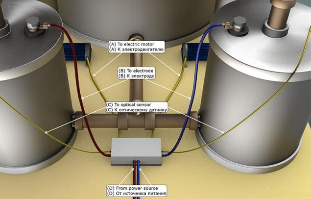
The main purpose — control of the process of generation and accumulation of gas (oxygen/hydrogen), obtained as a result of electrolysis.
In the initial state, the device delivers a power supply voltage (D), the electrodes of the electrolysis chambers (B). As a result, in the electrolytic cells begins to form and accumulate gas, and the water level gradually decreases. As soon as one of the optical water level sensors © will show that it has reached the lower limit (i.e., gas in the electrolysis cell has accumulated enough), the device must disconnect the supply voltage to the electrolysis chamber (B) and to use one of the motors of the compressor (A), completing one full cycle of the piston. In the case that the lower the level of water is reached simultaneously in 2 electrolysis chambers, the device must provide a sequential operation of the compressors (otherwise, voltage may not be enough to perform a cycle of operation of the compressor). After the completion of the cycle of operation of the compressor, the device should be return in its original condition and apply voltage to the electrodes of the electrolysis chambers.
Gas-storage chamberthe Primary purpose — the accumulation, storage and supply of gas (oxygen/hydrogen) to the electric batteries.
Gas-storage chamber is a cylinder with a set of holes through which gas is supplied to the chamber ©, is supplied to the power generating battery (A) and returns (B), and ensure the output water from the system (D). The volume of the gas-storage chamber is directly proportional to the ability of the system to accumulate energy, and is limited only by the physical dimensions of the camera itself.
Turbine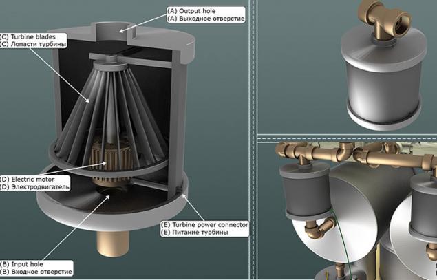
The main purpose — to provide circulation of gas (oxygen/hydrogen) in the electric batteries.
The gas from the gas-storage chamber that projects into the chamber of the device from the hole (B). Further, with the turbine blades © and centrifugal forces, a gas is blown into the outlet (A). The work of the turbine blades © provided by an electric motor (D) which is fed through connector (E).
Turbine, perhaps the most controversial of all modules of the concept. On the one hand, my meager knowledge of chemistry say that the circulating reactants react better to chemical reactions. On the other hand, I have not found any confirmation or refutation of the fact that active circulation of the gas will increase the efficiency of electric cells. In the end, I decided to include this device in design, but its impact on the efficiency of the system should be checked.
Electricity battery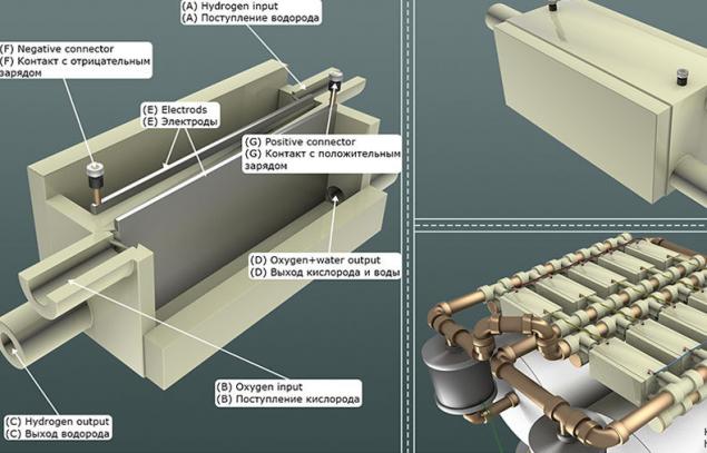
The main purpose is generation of electric current from a chemical Union of oxygen and hydrogen.
The oxygen and hydrogen entering the respective chambers through the holes (A) and (B) enters into a latent chemical reaction in the electrodes (E) formed by the electric current that is passed to the consumer via the contacts (F) and (G). By the chemical Union of oxygen and hydrogen in an oxygen chamber will be formed a large amount of water.
Perhaps the most interesting device. In the preparation of the design of this module I used public information available on the site for Honda (at the time of writing, there were several references, including documents, at the time of publishing, working there is only one).
The main problem is that Honda suggests to use as electrodes (E) platinum [Pt] plate. What makes the whole construction prohibitively expensive. But I am sure that it is possible to find a much cheaper (national) chemical composition for electrodes of electric cells. In the extreme case, you can always burn hydrogen in an internal combustion engine, but it significantly drops the efficiency of the whole structure, and the complexity and cost increase.
Drainage system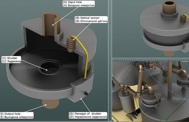
The main purpose — to ensure the withdrawal of water from the gas-storage chamber.
Water coming through the hole (A) into the chamber of the drainage system, it gradually accumulates, which is fixed optical sensor (B). As filling the chamber with water, the control system (D) opens the valve © and the water comes out through the hole (E).
It is important to consider that in the absence of power, the valve must be closed (for example, emergency situations). Otherwise, it is possible that when large amounts of hydrogen and oxygen will get into the sump, which can lead to detonation.
A sump for water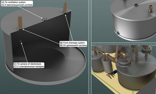
Primary purpose — the accumulation, storage and degassing of water.
Water from drainage system through the hole (B) into a chamber where it is degassing. The released oxygen and hydrogen exits through a vent (A). Settled and ready for electrolysis of water fed to the electrolysis chamber through the opening ©.
It should be noted that the water coming from the drainage system will be highly saturated with gas (oxygen/hydrogen). You must implement the mechanisms of the water degassing before its feeding to the electrolysis chamber. Otherwise it will affect the efficiency and safety of the system.
Management of electric power plants (stabilizer, inverter)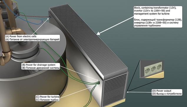
The main purpose — preparing of electricity generated for supply to consumer, nutrition and management of drainage systems and turbines.
Coming from the electric cell voltage (A), is fed to the transformer/stabilizer, where it is leveled to 12 volts. The stabilized voltage is supplied to the inverter and control system internal devices. The inverter voltage of 12 volts DC is converted to 220 volts AC (50 Hertz), and then supplied to the consumer (D).
The control device provides power for the drainage system (B) and turbines ©. Moreover, the device monitors the operation of turbine when the load increases from the consumer, increases the speed, the intensity of the stimulating energy to the power generating panels.
Features of operationWhen mechanical operation of the device became more or less clear, I propose to consider the characteristics (limitations) of use.
The installation must always be in a perpendicular position with respect to gravity. Because the mechanics of the operation of the system is widely used gravitational attraction (the primary accumulation of gas, drainage system, etc.). Depending on the level of deviation from this condition, the unit either will reduce the efficiency, if any, will be inoperative; With an eye on the previous item (for the same reasons), we can conclude that for the normal operation of the unit, it must be at rest (i.e., must be permanently installed) and the machine must operate only in open spaces (outside, on the street). Since the installation constantly produces free oxygen and hydrogen within a closed space, it will lead to the accumulation and subsequent detonation of these gases. Accordingly, within the confined space, operation of the device is unsafe. Disadvantages of the presented design
Presented in the article design is the 1st version of my idea. Ie all is the one that I originally planned. Accordingly, in the process of implementation of the concept, I saw some flaws/bugs, but to alter the scheme did not (because this would lead to an endless, iterative process improvements/enhancements, this article has not been published). But what I really caught my eye, I can't either, so I will just briefly describe those defects that must be corrected.
Since diffusion processes has not been canceled, in an oxygen gas-storage chamber to receive and accumulate hydrogen and, respectively, in the hydrogen chamber are similar processes. As a result, this will lead to detonation of the gas in the corresponding gas-storage chamber. This situation needs to be provided and in the construction of gas-storage chambers need to add partitions to absorb the blast wave. Also, the gas-storage chamber must be equipped with valves to release gas under positive pressure; In the present design, there is no mechanism for indicating energy storage. Accordingly, the installation of pressure sensor in the gas-storage chamber will allow to realize the display of accumulated energy (actually gas, but since we the output is electricity, it is indirectly obtained energy). Also, if the maximum pressure is reached in both chambers, the process gas can be stopped (to setup didn't work for nothing); the Current design of water settling chamber is not effective enough. Quite a lot of polluted water will fall directly into the electrolysis chamber, which will adversely affect the efficiency of the installation. In an ideal situation, the design must be redone so that the hydrogen and oxygen do not overlap (i.e., two independent circuits). In a simple embodiment, the design of water settling should be bilocular (perhaps even triple); If the device and the location of the compressor to rest, over time, in the chamber of the compressor and oculocephalic tubes condensation, which will reduce the efficiency of the compressor (or even make it unusable). Therefore, as a minimum, the compressor should turn on, and ideally, replace the mechanical compressor, for example, photoelectrically. ConclusionIn the end, if I have not made a fundamental error (for example, in the power generating device battery), turn the device energy storage, characterized by simplicity of design (and therefore reliability) with a relatively compact size (in relation to the amp/hours to the volume), devoid of any serious operational constraints (for example, operation at negative ambient temperatures). Moreover, the restrictions described in "operating Features", theoretically, can be eliminated.
Unfortunately, due to various circumstances, I probably won't be able to build and test the device described. But I hope that somebody, someday, will begin to make and sell something like that, and I'll be able to buy it.
Perhaps there are equivalents of the device described, but I such information not found (maybe bad looking).
In General, forward to a bright, clean future!!! published
Author: Kyrylo Kovalenko P. S. And remember, only by changing their consumption — together we change the world! © Join us at Facebook , Vkontakte, Odnoklassniki
Source: geektimes.ru/post/266360/
And it seems modern technology could provide decent device elektrogeneratory (modern solar panels already have an acceptable efficiency and life, to the wind turbines is also critical of the comments there), but the system of accumulation and storage of electricity, are most of batteries have some significant drawbacks (high cost, low capacity, short life, poor performance characteristics at low temperatures, etc.). And these disadvantages make the whole concept of individual, renewable electricity, unattractive to ordinary citizens.
In this article I propose to explore the concept of individual hydrogen storage of electricity, which, in a certain perspective, can replace the classic batteries.
NotesAll the images are purely conceptual in nature, the design of the engineering model will necessarily have to review all the sizes and features of the device components; I assume that somewhere described analog device, it is even possible there are commercial samples, but I didn't find anything similar. The General concept (principle of operation)

Despite the fact that the design was very cumbersome, the principle of operation is quite simple. Coming from a renewable source (solar panel, windmill, etc.) the electric current is fed into two electrolysis chambers (A), where the result of the electrolysis process begins to accumulate oxygen/hydrogen.
The resulting oxygen/hydrogen with a compressor (B) is pumped into the gas-storage chamber ©. From the gas-storage chamber ©, oxygen/hydrogen is supplied to the power generating battery (E), and then not participating in the reaction of oxygen/hydrogen, and the resulting reaction water is returned to the gas-storage chamber. The resulting chemical Union of oxygen and hydrogen, the electric current supplied to the transformer, then to the inverter and the control unit of the turbine/drain valve (H). With inverter, electric current is supplied to the consumer.
Accumulated in the gas-storage chamber water through the drainage mechanism (F) is transferred to the storage tank (G) and back to the electrolysis chamber.
Next, I suggest a closer look at the mechanics of operation of the system components.
The electrolysis chamber isthe Main purpose — the development and initial accumulation of oxygen/hydrogen, and passes to the compressor.

Coming into contact (A) electric current enters the electrode © where he begins the process of electrolysis of water in the chamber. Gas gradually accumulate in the top of the camera and getting directly to the compressor through the hole (E), pushes water through the opening (B) back into the tank. Thus there is a primary accumulation of gas before injection into the gas-storage chamber of the compressor. The whole process of primary accumulation of gas is controlled by optical (laser) sensor (D), the readings of which are transmitted to the control device.
Compressor

The main purpose of the pump is obtained in the electrolysis of the gas in the gas-storage chamber.
Gas (oxygen/hydrogen) from the electrolysis chamber into the chamber of the compressor through the valve (A). When the gas in the chamber of the compressor is accumulated in sufficient quantity (the signal comes from the optical sensor electrolysis chamber), activates the electric motor (F) and a piston ©, the accumulated gas is pumped into the gas-storage chamber through the valve (B).
The presence of the compressor allows us to create a gas-storage chamber pressure, which improves the efficiency of the electric cells.
It is very important to analyse the structure of the compressor (engine power, transmission gear ratio, the chamber volume of the compressor, etc.) so that the compressor could fully work (to develop pressure) from the renewable energy power source.
Management system electricity supply

The main purpose — control of the process of generation and accumulation of gas (oxygen/hydrogen), obtained as a result of electrolysis.
In the initial state, the device delivers a power supply voltage (D), the electrodes of the electrolysis chambers (B). As a result, in the electrolytic cells begins to form and accumulate gas, and the water level gradually decreases. As soon as one of the optical water level sensors © will show that it has reached the lower limit (i.e., gas in the electrolysis cell has accumulated enough), the device must disconnect the supply voltage to the electrolysis chamber (B) and to use one of the motors of the compressor (A), completing one full cycle of the piston. In the case that the lower the level of water is reached simultaneously in 2 electrolysis chambers, the device must provide a sequential operation of the compressors (otherwise, voltage may not be enough to perform a cycle of operation of the compressor). After the completion of the cycle of operation of the compressor, the device should be return in its original condition and apply voltage to the electrodes of the electrolysis chambers.
Gas-storage chamberthe Primary purpose — the accumulation, storage and supply of gas (oxygen/hydrogen) to the electric batteries.
Gas-storage chamber is a cylinder with a set of holes through which gas is supplied to the chamber ©, is supplied to the power generating battery (A) and returns (B), and ensure the output water from the system (D). The volume of the gas-storage chamber is directly proportional to the ability of the system to accumulate energy, and is limited only by the physical dimensions of the camera itself.
Turbine

The main purpose — to provide circulation of gas (oxygen/hydrogen) in the electric batteries.
The gas from the gas-storage chamber that projects into the chamber of the device from the hole (B). Further, with the turbine blades © and centrifugal forces, a gas is blown into the outlet (A). The work of the turbine blades © provided by an electric motor (D) which is fed through connector (E).
Turbine, perhaps the most controversial of all modules of the concept. On the one hand, my meager knowledge of chemistry say that the circulating reactants react better to chemical reactions. On the other hand, I have not found any confirmation or refutation of the fact that active circulation of the gas will increase the efficiency of electric cells. In the end, I decided to include this device in design, but its impact on the efficiency of the system should be checked.
Electricity battery

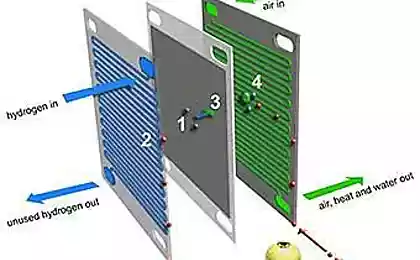
The main purpose is generation of electric current from a chemical Union of oxygen and hydrogen.
The oxygen and hydrogen entering the respective chambers through the holes (A) and (B) enters into a latent chemical reaction in the electrodes (E) formed by the electric current that is passed to the consumer via the contacts (F) and (G). By the chemical Union of oxygen and hydrogen in an oxygen chamber will be formed a large amount of water.
Perhaps the most interesting device. In the preparation of the design of this module I used public information available on the site for Honda (at the time of writing, there were several references, including documents, at the time of publishing, working there is only one).
The main problem is that Honda suggests to use as electrodes (E) platinum [Pt] plate. What makes the whole construction prohibitively expensive. But I am sure that it is possible to find a much cheaper (national) chemical composition for electrodes of electric cells. In the extreme case, you can always burn hydrogen in an internal combustion engine, but it significantly drops the efficiency of the whole structure, and the complexity and cost increase.
Drainage system

The main purpose — to ensure the withdrawal of water from the gas-storage chamber.
Water coming through the hole (A) into the chamber of the drainage system, it gradually accumulates, which is fixed optical sensor (B). As filling the chamber with water, the control system (D) opens the valve © and the water comes out through the hole (E).
It is important to consider that in the absence of power, the valve must be closed (for example, emergency situations). Otherwise, it is possible that when large amounts of hydrogen and oxygen will get into the sump, which can lead to detonation.
A sump for water

Primary purpose — the accumulation, storage and degassing of water.
Water from drainage system through the hole (B) into a chamber where it is degassing. The released oxygen and hydrogen exits through a vent (A). Settled and ready for electrolysis of water fed to the electrolysis chamber through the opening ©.
It should be noted that the water coming from the drainage system will be highly saturated with gas (oxygen/hydrogen). You must implement the mechanisms of the water degassing before its feeding to the electrolysis chamber. Otherwise it will affect the efficiency and safety of the system.
Management of electric power plants (stabilizer, inverter)

The main purpose — preparing of electricity generated for supply to consumer, nutrition and management of drainage systems and turbines.
Coming from the electric cell voltage (A), is fed to the transformer/stabilizer, where it is leveled to 12 volts. The stabilized voltage is supplied to the inverter and control system internal devices. The inverter voltage of 12 volts DC is converted to 220 volts AC (50 Hertz), and then supplied to the consumer (D).
The control device provides power for the drainage system (B) and turbines ©. Moreover, the device monitors the operation of turbine when the load increases from the consumer, increases the speed, the intensity of the stimulating energy to the power generating panels.
Features of operationWhen mechanical operation of the device became more or less clear, I propose to consider the characteristics (limitations) of use.
The installation must always be in a perpendicular position with respect to gravity. Because the mechanics of the operation of the system is widely used gravitational attraction (the primary accumulation of gas, drainage system, etc.). Depending on the level of deviation from this condition, the unit either will reduce the efficiency, if any, will be inoperative; With an eye on the previous item (for the same reasons), we can conclude that for the normal operation of the unit, it must be at rest (i.e., must be permanently installed) and the machine must operate only in open spaces (outside, on the street). Since the installation constantly produces free oxygen and hydrogen within a closed space, it will lead to the accumulation and subsequent detonation of these gases. Accordingly, within the confined space, operation of the device is unsafe. Disadvantages of the presented design
Presented in the article design is the 1st version of my idea. Ie all is the one that I originally planned. Accordingly, in the process of implementation of the concept, I saw some flaws/bugs, but to alter the scheme did not (because this would lead to an endless, iterative process improvements/enhancements, this article has not been published). But what I really caught my eye, I can't either, so I will just briefly describe those defects that must be corrected.
Since diffusion processes has not been canceled, in an oxygen gas-storage chamber to receive and accumulate hydrogen and, respectively, in the hydrogen chamber are similar processes. As a result, this will lead to detonation of the gas in the corresponding gas-storage chamber. This situation needs to be provided and in the construction of gas-storage chambers need to add partitions to absorb the blast wave. Also, the gas-storage chamber must be equipped with valves to release gas under positive pressure; In the present design, there is no mechanism for indicating energy storage. Accordingly, the installation of pressure sensor in the gas-storage chamber will allow to realize the display of accumulated energy (actually gas, but since we the output is electricity, it is indirectly obtained energy). Also, if the maximum pressure is reached in both chambers, the process gas can be stopped (to setup didn't work for nothing); the Current design of water settling chamber is not effective enough. Quite a lot of polluted water will fall directly into the electrolysis chamber, which will adversely affect the efficiency of the installation. In an ideal situation, the design must be redone so that the hydrogen and oxygen do not overlap (i.e., two independent circuits). In a simple embodiment, the design of water settling should be bilocular (perhaps even triple); If the device and the location of the compressor to rest, over time, in the chamber of the compressor and oculocephalic tubes condensation, which will reduce the efficiency of the compressor (or even make it unusable). Therefore, as a minimum, the compressor should turn on, and ideally, replace the mechanical compressor, for example, photoelectrically. ConclusionIn the end, if I have not made a fundamental error (for example, in the power generating device battery), turn the device energy storage, characterized by simplicity of design (and therefore reliability) with a relatively compact size (in relation to the amp/hours to the volume), devoid of any serious operational constraints (for example, operation at negative ambient temperatures). Moreover, the restrictions described in "operating Features", theoretically, can be eliminated.
Unfortunately, due to various circumstances, I probably won't be able to build and test the device described. But I hope that somebody, someday, will begin to make and sell something like that, and I'll be able to buy it.
Perhaps there are equivalents of the device described, but I such information not found (maybe bad looking).
In General, forward to a bright, clean future!!! published
Author: Kyrylo Kovalenko P. S. And remember, only by changing their consumption — together we change the world! © Join us at Facebook , Vkontakte, Odnoklassniki
Source: geektimes.ru/post/266360/


12 habits that you need to deal in the next 12 months
Super effective detox: drink with Cayenne pepper