1367
The control system of mini-blimp
Good afternoon, dear reader, your attention is given a project to develop a system touch control mini-blimp.
The task of management is the movement of the airship on the line. Was also implemented a simple remote control system.
The object of control is a mini-blimp designed to EIM of Chair, Tsure.
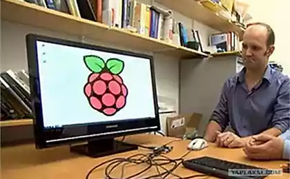
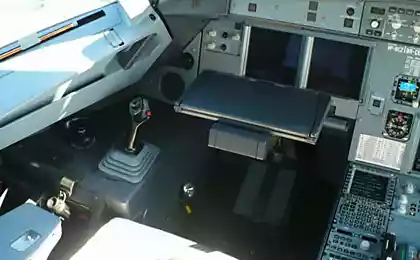
Figure 1 - General view of the mini-blimp.
The project aims to: develop a vision system for the detection of a line (path of movement); development of the course controller that takes into account the factors of the line position and angle of the line relative to the airship; development height adjuster; Development of a remote control system.
1. Analysis of tasks and task h4> Develop a system touch control is based on a mini-airship designed on the Department of EIM.
The task of management is the movement of the airship on the line. Was also implemented a simple remote control system.
The object of control is a mini-blimp designed to EIM of Chair, Tsure.
Figure 1 - General view of the mini-blimp.
The project aims to: develop a vision system for the detection of a line (path of movement); development of the course controller that takes into account the factors of the line position and angle of the line relative to the airship; development height adjuster; Development of a remote control system.
1. Analysis of tasks and task h4> Develop a system touch control is based on a mini-airship designed on the Department of EIM.
Mini airship includes a shell on the public components, namely a variety of foil balloons.
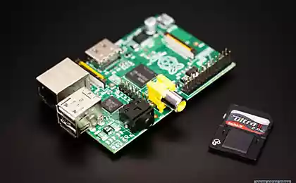
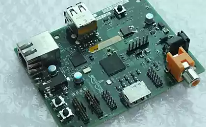
The hardware part of the mini-blimp consists of
- - SBC raspberry pi;
- - Wide Web Cameras Genius WideCam 1050;
- - ultrasonic sensor height hc-sr05;
- - two electric motors;
- - servo deflection thrust;
- - the power subsystem.
Airship engines have the ability to set the maximum speed of rotation in 3200. / Min. Operating voltage 7.4 volt motors. Engines are spaced from the center of the airship at 25 cm., And are at the lowest point of the airship.
2. Vision System h4>
2.1. Block diagram of a vision system h5>
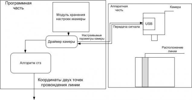
Figure 2 - Block diagram of the system of technical vision mini-blimp.
Vision system consists of hardware and software parts. The hardware part is related to the software part of a wired connection, which already passed the generated signal format MJPG.
In the hardware part includes a web camera.
As part of the program include:- - driver camera for video and image format MJPG job camera settings;
- - image processing module.
2.2. Development of functional circuit h5> In view of the selected treatment method and algorithm for determining the location of the line (which will be discussed in the next chapter under) were identified in the software implementation of the following subtasks:
- - configure the internal camera parameters;
- - get a picture with the camera;
- - convert the image format from MJPG in color format HSV;
- - to organize search by the intersection of color matching;
- - implement the algorithm for determining the coordinates of the intersection point,
- - filtering out not useful signal;
- - implement the integration unit FCZ with power regulator direction.
2.3. The algorithm h5> As you know, any two points in space can be laid straight. In this case, before the vision system mini-blimp seeks definitions laid lines. The first stage of image processing will be the search for these two points, which was laid our line.
Identify areas of interest on our picture to find these points. Optimal location area of interest will be gaps Mezhuyev 1/3 vertical part of the frame and 2/3. as shown in Figure 4, the blue lines.
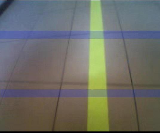
Figure 3 - Optimal location area of interest.
Criterion optimal location area of interest is the fact that the lower part of the zone of interest is perpendicularly down from the mini-blimp, and the top is not at the border of the frame, which minimizes the distortion of the image area.
The height of each of the zones is 10 pixels.
The point of intersection with the line defined by the corresponding pixel color specified. The color space of the vision system HSV.
Phase 2 of the algorithm on each area of interest.
1. Determining a predetermined color occurs in the array whose width is the width of the frame received from the camera. Each array element is a mean value of 10 pixels in the column zone of interest. Thus averaged color noise coming from the camera. The array has 3 rows, each of which corresponds to channels HSV. At the output we get a one-dimensional array in which the value of "1" denotes the pixel address corresponding to a given color, the value "0" denotes the address of pixels that do not match a specific color.
& lt; code & gt; for (x = 0; x & lt; width; x ++) {offset = x * nchannels; for (y2 = 35; y2 & lt; 46; y2 ++) {uchar * data = (uchar *) (hsv- & gt; imageData + y2 * step); r = data [offset + 2]; g = data [offset + 1]; b = data [offset]; h [y2-35] = b; s [y2-35] = g; v [y2-35] = r; } H [10] = (h [0] + h [1] + h [2] + h [3] + h [4] + h [5] + h [6] + h [7] + h [8 ] + h [9]) / 10; s [10] = (s [0] + s [1] + s [2] + s [3] + s [4] + s [5] + s [6] + s [7] + s [8] + s [9]) / 10; v [10] = (v [0] + v [1] + v [2] + v [3] + v [4] + v [5] + v [6] + v [7] + v [8] + v [9]) / 10; if ((h [10] & lt; h1 & amp; & amp; h [10] & gt; h2) & amp; & amp; (v [10] & gt; ss) & amp; & amp; (s [10] & gt; vv)) {st [x] = 1;} else {st [x] = 0;} & lt; / code & gt; pre>
2. Determination of the left and right boundaries of the zone of intersection.
According to the input array are filled two arrays of the same dimension. Call them st1 and st2. Filling algorithm implemented arrays cycle in which some variable increases linearly if the element of the input array is 1, and exponentially decreases when the element under consideration is equal to 0, and is recorded in the next array element st1. To form the array st2, the input array is viewed from the end. As a result, st1 and st2 arrays can be graphically represented as follows (Fig. 5)
Figure 5 - Graphical representation of arrays st1 and st2.
Useful signal is the most extensive area of color definition. Noise is small false positives, which can be observed on the record figure 7. The coordinates x maximum element red graph (st1), is the right side of a line across the zone of interest. The x coordinate of the maximal element of blue graphics (st2), is the left side of the line across the zone of interest.
Listing
 & lt; code & gt; double sum = 1; double sum2 = 1; for (x = 0; x & lt; width; x ++) {if (st [x] == 1) {sum = sum + 1; st1 [x] = sum;} else {sum = sum / 1.05; st1 [x] = sum;} if (st [width-x] == 1) {sum2 = sum2 + 1; st2 [width-x] = sum2;} else {sum2 = sum2 / 1.005; st2 [width-x] = sum2} } & lt; / code & gt;  pre>

 After the formation of arrays st1 and st2, are the maximal elements of the array, and the calculated center of the intersection zone. By applying the described steps to the second crossing zone, at the outlet, we have coordinates of points through which the shedding.

Applying common way define the zone of confidence in the next frame, as in the previous facility was not used, since such a method and showed acceptable results of noise in the output parameters. Also the use of this method would not decrease CPU usage, since we are dealing only with multiple enumeration of two arrays with a width of 176 pixels, the resolution of all of the image is 176x144 pixels.
3. Regulator direction h4>
3.1. Block diagram of the controller in the control system h5>
Figure 4 - Block diagram of the controller direction.
Software implementation consists of:
- - fuzzy controller;
- - mathematical calculation module pivot line;
- - Shimano software.
The hardware implementation consists of:
- - Drivers Engine L293DNE;
- - left and right electric motor.
Application software is due to the absence in Shima used SBC Raspberry pi hardware Shima.
Motor driver is used to amplify the PWM signal.
3.2. Design of fuzzy controller. H5>
3.2.1. Definition of inputs and outputs of the system created. H6> As for the precise passing mini-blimp on line to be considered as deviations from the axis line of the airship, and rotation about the same axis, respectively, the input parameters of the controller to set the variable deviation ( OFF) and rotation (PIW). Regulator output variable will be the parameters of the output PWM signal as a percentage. The output variable effects on left engine is designated as (LEV), the right engine, respectively (rules)
3.3.2. Task for each of the input and output variables of the membership function with terms h6> Output Accessories terms left and right of the engine would have to be set, figured nonlinear parameters of the DC motor PWM relative impact. But as the flight speed of the airship suggest small deviation linear motors, the terms were set for an ideal engine with absolute linear characteristic.
Figure 5 - Baths of output variables LEV and rules.
Input variables are deviations from the longitudinal axis of the airship line and turn the line of this axis are obtained as a result of the vision system and a mathematical calculation of the angle of the module, which has a camera distortion performance. Indicators camera distortion can be put in the input term OFF and Brokers. Since the accuracy of positioning and trajectory line-out to no requirements, the performance of the distortion can be ignored. In this task, the term tuned picture distortion camera or adjust the terms on them. Thermae were changed around, which was a sufficient condition for the functioning of the system.
Figure 6 - Therm OFF and Brokers.
3.2.3. Develop database of inference rules implemented fuzzy system h6> To develop the rule base is necessary to designate the linguistic variables (terms) easy to understand names.
Figure 7 - Designation of the term.
1 OFF - hard left.
OFF 2 - to the left.
OFF 3 - center.
OFF 4 - right.
OFF 5 - strongly to the right.1 Stand - hard left.
Stand 2 - left.
Stand 3 - center.
Stand 4 - right.
Stand 5 - hard to the right.LEV 1 - very weak.
LEV 2 - weakly.
LEV 3 - medium.
LION 4 - strongly
LION 5 - very much.RIGHTS 1 - very weak.
Rule 2 - weakly.
RIGHTS 3 - medium.
RIGHTS 4 - strongly
Rule 5 - very Accordingly, these names, considering that the mini-blimp controlled raznotyagom engines establish communication term.
block rules:
IF OFF strongly left, Leo is very weak and the rules are very strongly.
IF OFF left, Leo is weak. And the right of the strong
IF OFF center, Leo average. And right middle.
IF OFF right, Leo strengths and rights of the weak.IF OFF strongly to the right, Leo is very strong. And the rule is very weak.
IF Brokers strongly left, Leo is very weak. And the rule is very strong.
IF Stand to the left, Leo is weak. And the right of the strong
IF Stand right, Leo strengths and rights of the weak.
IF Brokers strongly to the right, Leo is very strong. And the rule is very weakly You can see that for the input variable Stand no connectivity averages. This is due to the fact that when correctly oriented relative to the longitudinal axis of the airship line and deviations from it, the average term of motors pulling the input values to the middle of what is wrong in this position of the airship.
In this system, the fuzzy algorithm is an algorithm Mamdani defuzzification.
This algorithm describes several sequentially executes steps, with each successive stage takes as input the values obtained in the previous step.
3.2.4. Analysis of the process of the fuzzy system h6>
To analyze the operation. Were constructed correlation portraits regulator. In the following figures the Y axis is the input variable Stand, X-axis input variable to OFF. The color of the pixel corresponds to an input variable for each motor, -minimum white, black - max.
Figure 8 - Correlation portraits output value of the fuzzy system for the left and right of the engine, the intersection of the correlation portraits.
The last figure we see the result of crossing two portraits of correlation with the use of selected pixels with the same color and location. From the result of the intersection can be determined under any input conditions are the same values of engine power. Characteristic black square area on the edges give the boundary terms with truncated top.
Below are the results of the simulation of fuzzy controller on the location line in the frame marked in red. The right side of the video, you can see the PWM signal levels for the left and right engine, respectively. The left Chisti located input and output terms toiletries.
4. Height Adjuster h4>
4.1. Block diagram of the controller h5>
Figure 9 - Block diagram of the height adjuster.
Software implementation consists of:- PI controller on fuzzy logic;
- math module calculating distances;
- Software Shima;
The hardware implementation consists of a- Servo vectored thrust engines;
- Ultrasonic sensor HC-SR05.
4.2. Design of fuzzy controller h5>
4.2.1. Definition of inputs and outputs of the system created h6>
Input parameter of the fuzzy controller is the error from the desired height. The output variable is the proportional part of the PI component of the hybrid controller.
The integral is the output of the entire system and realized just how cumulative variable representing the position of the servo.
4.2.2. Task for each of the input and output variables of the membership function with terms h6> Define output accessory terms, guided uniform distribution over the surface of the term. The nonlinearity of the output of fuzzy system is defined by terms of the input variable.
Figure 10 - Theremin output variable OUT
Input variable error terms of the height shown in the figure below.
Figure 11 - Baths input variable height
4.2.3. Develop database of inference rules implemented fuzzy system h6> To develop the rule base, you must define the linguistic variables (terms) easy to understand names.
Figure 12 - Designation term
height 1- strong deviation down.
Height 2 - downward deflection.
Height 3 - no deviation.
Height 4 - upward deflection.
Height 5 strong deviation topOutput 1 - high positive
Output 2 - positive
Output 3 - zero
Output 4 - negative
Output 5 - high negative
Liability is established a direct link term.
block rules:
IF Height: strong deviation down, the output: high positive
IF Height: downward deviation, output: positive
If the height: no deviation, the output: Zero
IF Height: upward deflection, the output: negative
IF Height: strong deviation top, then the output: high negative
5. Remote Control System h4> The remote control system is implemented in the management of the difference of torque engines. Implementation principles borrowed from computer games when pressing realizes smooth deviation of torque and release - a smooth return, so to some extent possible to maintain the difference between the traction motors.
Signaling keystrokes via wireless channel wi-fi via ssh, in which the base of the terrestrial habitats (PC) keyboard interface is transmitted to the remote computer.
Sending video stream is done in the same way because the ssh protocol allows us to observe the screen of the remote machine.
6. Experimental study of the system h4> The designed system was investigated in the laboratory. Vision system detects the position of the line and transmits the coordinates of the intersection points in the direction of the controller unit.
Job vision system
Span mini-blimp
Stability of the system of adjustment of height and direction turned achieve requisitions coefficient. proportional increase in the output effects of fuzzy systems.
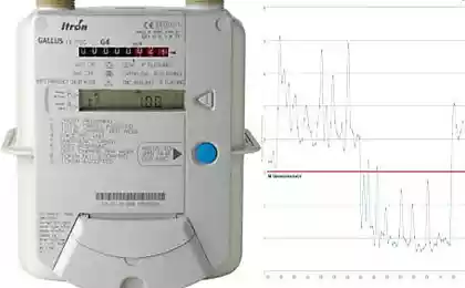
Figure 13 - The provisions of the thrust vector and the height sensor dirigible. Specifies the height of 80 cm.
On the data obtained, we see a high noisy signal with a sensor error in the development of the system was not using the filter signal. The reason for not using the filter was the signal sensor test, which showed no big noisy signal of the sensor.