783
Digital Aircraft
via Shvonder
Argued that the old planes safer today because they contain fewer electronics. For example, A-320, I will try to explain how to secure and modern "computer" aircraft.
What is «Fly-by-wire»?
At the dawn of aviation control of the aircraft was carried out mechanically - with the help of ropes and rods connecting the controls (steering wheel and pedals) with ailerons and rudders napravlyaniya and height.
As the size and speed of the aircraft grew and physical effort required to manage the pilot. To help people came booster mechanisms (hydraulic actuators). Although they facilitate the work of the pilot, management is still carried out cables and rods. The reliability of such systems provides redundancy control rods, cables and actuators.
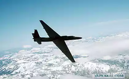
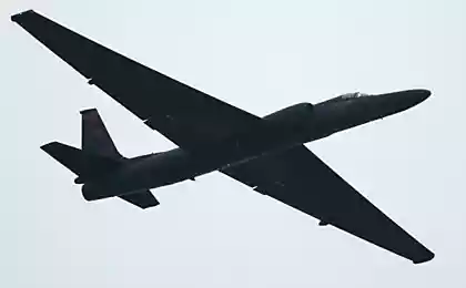
Both control schemes - and the mechanical booster - and still are used as a light aircraft, and for large aircraft, including on the SR-71 and AN-225 "Mriya».
In the mid-50s for military aircraft developed new, so-called statically unstable aerodynamic layout, enabling a significant increase in maneuverability, but do not allow to make the flight without constant correction. It was necessary to fend off emerging perturbations faster than they develop. Due to the low reaction rate of a person he was not able to solve this problem and to control statically unstable aircraft was developed by wire control system (or FBWCS Fly-by-wire, FBW). On the basis of data received from the sensors and controls, FBWCS shaped servo signals for the aerodynamic surfaces (ailerons and rudders). That is, a man ran FBWCS and FBWCS fly a plane.
First FBWCS were analog, and later there were digital. Now FBWCS used on virtually all combat aircraft and engaged in civil aviation. But in civil aviation, they are not for the purpose of svehmanevrennosti
Consider the implementation of the concept of Fly-by-Wire as an example of the aircraft A-320.
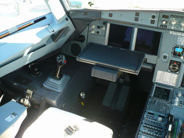
If you look into the cockpit A320, instead of steering wheels find joysticks (in the terminology Airbus- saydstika) on the side consoles. Each saydstik equipped with strain gauges whose data are processed by computer and given the current situation is transmitted to the actuators.
A320 has a flight control computer 7 - 2 computer ELAC (Elevator Aileron Computer), 3 computers SEC (Spoilers Elevator Computer) 2 computer FAC (Flight Augmentation Computer).
anticipating questions about the "hardware" - ELAC computers run on the Motorola 68000 processor, SEC - INTEL 80186. smile.gif
Each of these computers has 2 modules - Control Unit and Monitoring Unit. In fact, it is 2 independent devices to receive and process the same data. But if the Monitoring Unit detects a discrepancy between the results of our calculations with the results of calculations Control Unit, then the computer is considered to be faulty and its functions taken over by his "partner." To avoid possible errors, software Control Unit and Monitoring Unit developed razymi teams of programmers in different languages. *
Even in the event of complete failure pair, the other pairs can carry out its function. So for example, the stabilizer trim meets the computer ELAC2. In case of failure, features ELAC2 able to assume ELAC1, then SEC1, then SEC2. That is, in addition to working in parallel identical blocks there and duplication of functions between the different units. This provides multiple redundant flight control system.
Each computer has a self-diagnosis function on the following parameters - control processor (watchdog and checksums), control power, control inputs and outputs, feedback control. Diagnostics inputs provided by comparing identical signals received from different devices.
There are several levels - modes of flight control computers, which in the terminology of Airbus called "laws".
The first mode - NORMAL LAW. This mode is the main and most frequently used. The aircraft will be subject to the pilot, but will not exceed the critical values of the angle of attack, overload, pitch and roll and will also control the speed, not allowing the move limits the maximum and minimum speeds for the current flight mode. This mode remains in operation in case of failure of any of the 7 computers.
In case of refusal of several computers activate the second mode - ALTERNATE LAW. In this mode persists protection of critical overload, as well as against loss or speeding.
When multiple computer failure mode is activated tretity - DIRECT LAW. In this mode, the signals from saydstika not processed and fed directly to the servos.
In the case of complete failure of all the flight control computer 7, A-320 has a hydromechanical backup system at the rate and pitch.
And in conclusion. In the history of the A-320 crash was the fault of the equipment only once - in 1988, after which all aircraft have been finalized.
At the moment, it released around 5000 aircraft of this family.
Engineers at Boeing even more severe.
In each of the three computer systems Fly-by-Wire aircraft Boeing-777 in order to avoid errors the three processors from different manufacturers - Intel 80486, Motorola 68040 and AMD 29050. All of them perform the same task. Software written in ADA. However, each processor needs its own trim and the compiler, which also increases the reliability of the overall system. In identifying the differences in the results of the computer is turned off. Boeing calls the scheme «triple-triple redundant architecture».
And now a little review of national development - Remote control of the CDS-10 mK.
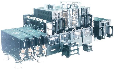
From 2007 to 2009 I worked at the electronics manufacturer (Elara, Cheboksary), lead engineer on this product. I write mostly from memory, as currently employed elsewhere and access to technical documentation have not. There was only a summary. This product is not a secret.
CDS-10 mK (CDS-10 mK Ser. 2) - 4-fold redundant analog-to-digital control system of the aircraft in the longitudinal, transverse and track channels. The system replaces the mechanical control wiring. This system is installed on the Su-30MK ... (mainly for the Indian Air Force) Parts
2 dual power supply. Power supply of the CDS from two independent sources of DC rated voltage 27V, operating in the buffer batteries and two independent three-phase AC voltage of 115V frequency of 400Hz. Withstands transients dc to 50 volts. CDS - life support system. The plane simply dropped if the CDS deny
Evaluators. Combined into several blocks and a wardrobe. In total, it consists of 60 modules (read - printed circuit boards). Produce processing signals from sensors and output signals to the executive steering gears. Evaluators work simultaneously and form a medium resulting signals. The system continues to operate with two independent failures in different channels calculators. That is, in case of failure in one of its calculators outputs begin to differ from the signals of other calculators. Exceeding (belittling) the specified threshold, the calculator is turned off and a signal to the voice informant, and the control panel. You can try to restart the control panel. If several faults signals becomes not compare with anything and the system goes into a rigid connection (in this mode control the fighter is almost impossible because it is unbalanced aerodynamic design and constantly leads). Not a single disaster-related failure of the CDS-10 mK was not. The accident was one such.
Sensors. Convert various physical parameters into electrical signals flight. Sensors in the CDS are completely independent from other systems. That is, for example, the navigation system (PNA) and the CDS have similar functionality for sensors. All sensors 4x duplicated. CDS "removes" flight following parameters:
- Static and dynamic pressure (DBP, DDD - absolute pressure sensor, differential pressure sensor) for measuring the speed and altitude. These parameters need to know, because at different altitudes different density of the air, and at different speeds, different resistance
- Angular velocity (CRS, REM - an angular velocity sensor, gyro sensor unit). Required for determining the angular velocity of rotation around their axes. CDS immediately returns the aircraft to its original position for any deviation glider
- The position of the control stick and pedals (DPR - redundant encoder). These sensors are converted into an electrical signal position control knob in two planes (roll, pitch) and pedals (course)
Boards. PP, PU - remote verification, remote control. Designed for testing performance of the CDS and the CDS control during operation as well as for monitoring performance and restart during flight
The steering machine. Designed to convert electrical signals into mechanical CDS. Mechanical signals pre-amplified hydraulic machines that are part of the CDS does not include modes
CDS operates in several modes: off and landing, flight refueling. Modes differ primarily transfer coefficient and the operation of individual deflecting surface. For example, in the "refueling" the plane is moving much more smoothly than in the "flight". During the flight, the system continuously monitors the position of the plane in space, speed, and direction of flight and manages flaperons, socks, canards, rudders and height and the deflection angle of the nozzles in the vertical plane.
The system has stops limiting conditions do not allow the pilot to bring the aircraft beyond its capabilities. When approaching the limit regimes pen pilot begins to tremble mightily, as if a plane falls apart right now, but in fact it is an imitation.
Production technology and quality control
The system has been fully implemented in the domestic element base. The manufacturer has its own mechanical workshop, a workshop for the production of printed circuit boards, microelectronics plant. The system is not sealed. All printed circuit boards have a moisture barrier in the form of 3 layers of varnish. Particularly sensitive compound is coated board. Supporting structures are manufactured on CNC machines.
Quality is controlled at all stages of production shops themselves, OTC and military establishment. Product Test Report comparable with 96 sheet magazine. After manufacturing system test about 2 weeks.
Other
The system takes the most severe tests, and in my opinion, is the most tenacious electronic product in an airplane. Her experience at temperatures -60..60 degrees for hours shaking on a vibrating table, polluting salts, sand, mushroom pairs. It weighs about 120 kg system. and very expensive, but it is a trade secret of the manufacturer.
Currently we developed a modern digital counterparts (eg, SIC-35), but the CDS-10 mK are still produced and used successfully.
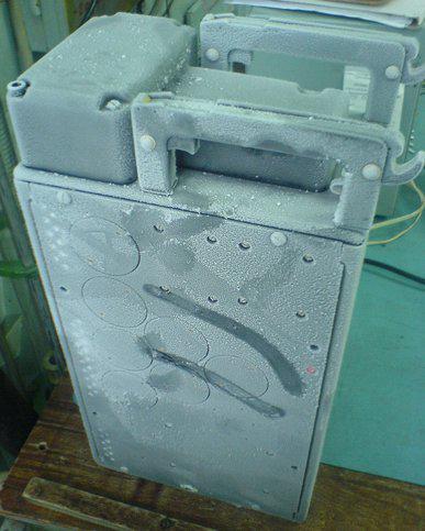
In Figure 3 - Power supply BP-58 from the SDU-10U, C (GC-27) after the tests at low temperature. This is an older system that is also still produced.
Source:
Argued that the old planes safer today because they contain fewer electronics. For example, A-320, I will try to explain how to secure and modern "computer" aircraft.
What is «Fly-by-wire»?
At the dawn of aviation control of the aircraft was carried out mechanically - with the help of ropes and rods connecting the controls (steering wheel and pedals) with ailerons and rudders napravlyaniya and height.
As the size and speed of the aircraft grew and physical effort required to manage the pilot. To help people came booster mechanisms (hydraulic actuators). Although they facilitate the work of the pilot, management is still carried out cables and rods. The reliability of such systems provides redundancy control rods, cables and actuators.
Both control schemes - and the mechanical booster - and still are used as a light aircraft, and for large aircraft, including on the SR-71 and AN-225 "Mriya».
In the mid-50s for military aircraft developed new, so-called statically unstable aerodynamic layout, enabling a significant increase in maneuverability, but do not allow to make the flight without constant correction. It was necessary to fend off emerging perturbations faster than they develop. Due to the low reaction rate of a person he was not able to solve this problem and to control statically unstable aircraft was developed by wire control system (or FBWCS Fly-by-wire, FBW). On the basis of data received from the sensors and controls, FBWCS shaped servo signals for the aerodynamic surfaces (ailerons and rudders). That is, a man ran FBWCS and FBWCS fly a plane.
First FBWCS were analog, and later there were digital. Now FBWCS used on virtually all combat aircraft and engaged in civil aviation. But in civil aviation, they are not for the purpose of svehmanevrennosti
Consider the implementation of the concept of Fly-by-Wire as an example of the aircraft A-320.

If you look into the cockpit A320, instead of steering wheels find joysticks (in the terminology Airbus- saydstika) on the side consoles. Each saydstik equipped with strain gauges whose data are processed by computer and given the current situation is transmitted to the actuators.
A320 has a flight control computer 7 - 2 computer ELAC (Elevator Aileron Computer), 3 computers SEC (Spoilers Elevator Computer) 2 computer FAC (Flight Augmentation Computer).
anticipating questions about the "hardware" - ELAC computers run on the Motorola 68000 processor, SEC - INTEL 80186. smile.gif
Each of these computers has 2 modules - Control Unit and Monitoring Unit. In fact, it is 2 independent devices to receive and process the same data. But if the Monitoring Unit detects a discrepancy between the results of our calculations with the results of calculations Control Unit, then the computer is considered to be faulty and its functions taken over by his "partner." To avoid possible errors, software Control Unit and Monitoring Unit developed razymi teams of programmers in different languages. *
Even in the event of complete failure pair, the other pairs can carry out its function. So for example, the stabilizer trim meets the computer ELAC2. In case of failure, features ELAC2 able to assume ELAC1, then SEC1, then SEC2. That is, in addition to working in parallel identical blocks there and duplication of functions between the different units. This provides multiple redundant flight control system.
Each computer has a self-diagnosis function on the following parameters - control processor (watchdog and checksums), control power, control inputs and outputs, feedback control. Diagnostics inputs provided by comparing identical signals received from different devices.
There are several levels - modes of flight control computers, which in the terminology of Airbus called "laws".
The first mode - NORMAL LAW. This mode is the main and most frequently used. The aircraft will be subject to the pilot, but will not exceed the critical values of the angle of attack, overload, pitch and roll and will also control the speed, not allowing the move limits the maximum and minimum speeds for the current flight mode. This mode remains in operation in case of failure of any of the 7 computers.
In case of refusal of several computers activate the second mode - ALTERNATE LAW. In this mode persists protection of critical overload, as well as against loss or speeding.
When multiple computer failure mode is activated tretity - DIRECT LAW. In this mode, the signals from saydstika not processed and fed directly to the servos.
In the case of complete failure of all the flight control computer 7, A-320 has a hydromechanical backup system at the rate and pitch.
And in conclusion. In the history of the A-320 crash was the fault of the equipment only once - in 1988, after which all aircraft have been finalized.
At the moment, it released around 5000 aircraft of this family.
Engineers at Boeing even more severe.
In each of the three computer systems Fly-by-Wire aircraft Boeing-777 in order to avoid errors the three processors from different manufacturers - Intel 80486, Motorola 68040 and AMD 29050. All of them perform the same task. Software written in ADA. However, each processor needs its own trim and the compiler, which also increases the reliability of the overall system. In identifying the differences in the results of the computer is turned off. Boeing calls the scheme «triple-triple redundant architecture».
And now a little review of national development - Remote control of the CDS-10 mK.

From 2007 to 2009 I worked at the electronics manufacturer (Elara, Cheboksary), lead engineer on this product. I write mostly from memory, as currently employed elsewhere and access to technical documentation have not. There was only a summary. This product is not a secret.
CDS-10 mK (CDS-10 mK Ser. 2) - 4-fold redundant analog-to-digital control system of the aircraft in the longitudinal, transverse and track channels. The system replaces the mechanical control wiring. This system is installed on the Su-30MK ... (mainly for the Indian Air Force) Parts
2 dual power supply. Power supply of the CDS from two independent sources of DC rated voltage 27V, operating in the buffer batteries and two independent three-phase AC voltage of 115V frequency of 400Hz. Withstands transients dc to 50 volts. CDS - life support system. The plane simply dropped if the CDS deny
Evaluators. Combined into several blocks and a wardrobe. In total, it consists of 60 modules (read - printed circuit boards). Produce processing signals from sensors and output signals to the executive steering gears. Evaluators work simultaneously and form a medium resulting signals. The system continues to operate with two independent failures in different channels calculators. That is, in case of failure in one of its calculators outputs begin to differ from the signals of other calculators. Exceeding (belittling) the specified threshold, the calculator is turned off and a signal to the voice informant, and the control panel. You can try to restart the control panel. If several faults signals becomes not compare with anything and the system goes into a rigid connection (in this mode control the fighter is almost impossible because it is unbalanced aerodynamic design and constantly leads). Not a single disaster-related failure of the CDS-10 mK was not. The accident was one such.
Sensors. Convert various physical parameters into electrical signals flight. Sensors in the CDS are completely independent from other systems. That is, for example, the navigation system (PNA) and the CDS have similar functionality for sensors. All sensors 4x duplicated. CDS "removes" flight following parameters:
- Static and dynamic pressure (DBP, DDD - absolute pressure sensor, differential pressure sensor) for measuring the speed and altitude. These parameters need to know, because at different altitudes different density of the air, and at different speeds, different resistance
- Angular velocity (CRS, REM - an angular velocity sensor, gyro sensor unit). Required for determining the angular velocity of rotation around their axes. CDS immediately returns the aircraft to its original position for any deviation glider
- The position of the control stick and pedals (DPR - redundant encoder). These sensors are converted into an electrical signal position control knob in two planes (roll, pitch) and pedals (course)
Boards. PP, PU - remote verification, remote control. Designed for testing performance of the CDS and the CDS control during operation as well as for monitoring performance and restart during flight
The steering machine. Designed to convert electrical signals into mechanical CDS. Mechanical signals pre-amplified hydraulic machines that are part of the CDS does not include modes

CDS operates in several modes: off and landing, flight refueling. Modes differ primarily transfer coefficient and the operation of individual deflecting surface. For example, in the "refueling" the plane is moving much more smoothly than in the "flight". During the flight, the system continuously monitors the position of the plane in space, speed, and direction of flight and manages flaperons, socks, canards, rudders and height and the deflection angle of the nozzles in the vertical plane.
The system has stops limiting conditions do not allow the pilot to bring the aircraft beyond its capabilities. When approaching the limit regimes pen pilot begins to tremble mightily, as if a plane falls apart right now, but in fact it is an imitation.
Production technology and quality control
The system has been fully implemented in the domestic element base. The manufacturer has its own mechanical workshop, a workshop for the production of printed circuit boards, microelectronics plant. The system is not sealed. All printed circuit boards have a moisture barrier in the form of 3 layers of varnish. Particularly sensitive compound is coated board. Supporting structures are manufactured on CNC machines.
Quality is controlled at all stages of production shops themselves, OTC and military establishment. Product Test Report comparable with 96 sheet magazine. After manufacturing system test about 2 weeks.
Other
The system takes the most severe tests, and in my opinion, is the most tenacious electronic product in an airplane. Her experience at temperatures -60..60 degrees for hours shaking on a vibrating table, polluting salts, sand, mushroom pairs. It weighs about 120 kg system. and very expensive, but it is a trade secret of the manufacturer.
Currently we developed a modern digital counterparts (eg, SIC-35), but the CDS-10 mK are still produced and used successfully.
In Figure 3 - Power supply BP-58 from the SDU-10U, C (GC-27) after the tests at low temperature. This is an older system that is also still produced.
Source:
