1163
Calculation of bridge
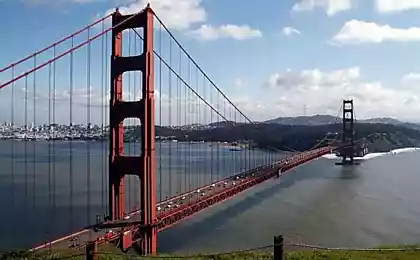
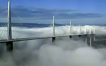
It's about the calculation of the bridge. A brief introductory post to the roots, to the best sources of the appearance of such structures. I think it will be interesting and drivers and pedestrians who see these objects every day, go over the bridge, go through it, stand in a traffic jam, etc.
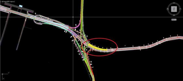
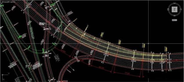
First things first get itself the task of designing, in the job has been all surveys (geological, surveying, etc., are not always available, of course, but in this example were all data on the design). We need an electronic (format AUTOCad) version of the plan-drawing interchange coordinates and scale. This will be the most important basis for the design of our bridge. Red oval circled our site directly junction
Here's a closer outcome desired location. On the instructions necessary to design a 5-Flying-pass the continuous composite bridges. Produces about a breakdown (yellow line - is the main structural dimensions) bridge to span (several tens stage approvals and other paperwork). In this example, we see that the length of the span will be approximately equal (not carp about the size of the arc, and so on - it is simply illustrative example and an overview about how it all happens): 52, 83 M + 53, 34 + 62 m 22 M + 77, 02 + 62 m, 24 m. Total length of our future bridge will be equal to approximately 307.65 m, which refers to extra-curricular bridges.
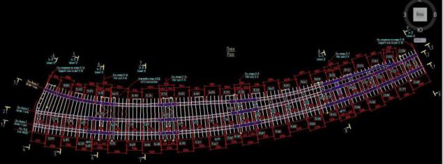
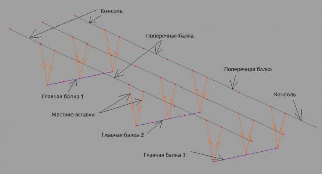
Further there is a detailed breakdown of the final bridge to span structures and superstructures - blocks. In this case, it is clear that the basis of the span of the bridge are 3 "guide" or 3 main beams. Top view of the superstructure:
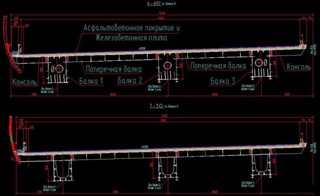
Let's look at a couple of cuts (6-6 and 7-7, for example) and that in fact it represents the construction of the superstructure of the bridge. As already mentioned above: the three main (supporting) element - the main beam. They are interconnected webs or cross beams for collaboration, cross beams at the edges - a console for the development dimension of the carriageway. Include all sizes construction along / across / on the plan. "Why have littered the horizon span?" - You might say. "First to Vodicka dripping" - I can tell. A second bridge is located on a bend on a small, but still bend, across the slope here is required for all regulations. The pillars on which rests (well, oil-oil, does not) span not shown here. The essence of the post - calculation of the superstructure of the bridge, not the supports (if interested, the theme was built on the calculation of support)
As a result, all sizes, dimensions and design details negotiated and approved by the customer. You can proceed to the calculation of the bridge itself, but rather the span of the bridge, just the part for which you, dear motorists vozite their ass from one bank to another. "But what is considered necessary, because everything has already drawn?" - You might say. I will answer you in a few steps:
1. On the basis of the construction of our bridge, we know that it consists of 3 metal boxes, which consist of vertical sheets (wall box), the upper and lower horizontal plates (upper and lower belt of the box, respectively). - Need to calculate the thickness, size and height of the sheet on the basis of all operating conditions (road category, traffic at the site, the climatic area in the end, what matters is not too small)
2. The reinforced concrete slab bridge (it is the one which then put asfaltik). She also suffers from external loads, it is necessary to calculate its interaction with the metal part of the superstructure, as well as its interaction with the wheel (automotive and extracurricular) load.
So, knowing all the dimensions, details, materials of construction of the superstructure can begin to integrate all the data to design programs of many different, I will focus on the complex, allows to model the three-dimensional structure of bridges, produce them in-depth consideration.
All such programs are based on the fundamental laws of physics, mechanics, strength of materials (Oo-oo-oo-oo-oo-oo, blonde, probably took a shiver when I remember the terrible things in the name of the university?).
We develop the basic design scheme of the bridge, it will be based on the use of plate-rod system. The program interface is hidden - semantic meaning do not see.
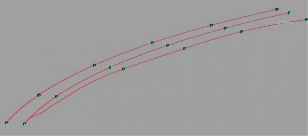
We start with the design "skeleton" beams span in the calculation program (those in the know - based on the calculation of the structural finite element). Each segment between red dot - an element of the main beam span. Black and green dots - a place bearing span to support (the program it looks like a travel ban construction at this point in a particular direction until).
Adding cross beams and brackets
Rigidly connecting the two special "fasteners" to work together (otherwise called - rigid insert). For clarity, I cut a piece of the span to have a general idea.
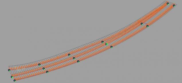
A general view of the entire core structure. Visualization points, limiting segments of elements removed, so the meat. But to understand the main beams, cross beams and brackets, can be rigid inserts. To illustrate the scale of the general structure:
Design scheme, consisting of bars, or finite elements ready. Now you need to describe each stem (element), to give it shape and material.
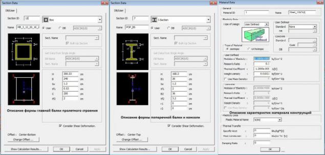
- For a description of the main beam, we use box section, wall thickness and assign zones. While all three beams principal throughout the length will be just that the cross-section (looking ahead to say that this is not the final version, but only the first iteration, then will the selection of cross-sections, depending on the results of the calculation, there may be any number as long as the selection It does not satisfy all the rules and regulations). Typically, in the first iteration (in other words - in a first approximation) the thickness of the wall sheets and belts are given based on experience.
-To Describe the cross-beams and I-beams console we take again ask-section, giving a wall thickness and a belt (as empirically appointed).
Well, and assign the material to our design described in the window of its characteristics, this example describes the characteristics of bridge steel 15HSND.
The most interesting stage. It is necessary to "dress" the cross sections on our rods. In other words - to designate the characteristics of the end elements of the cross-section and material. Dress, visualize:
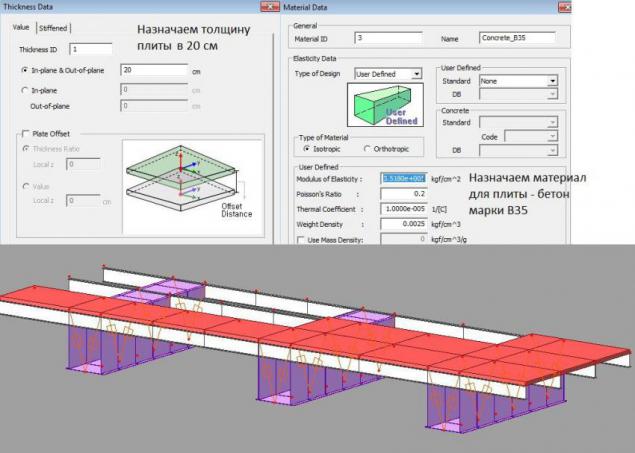
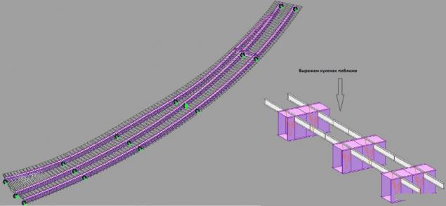
The metal part of the superstructure is ready. Getting the design of reinforced concrete slabs. Assigns the thickness of the material (in this case - is a concrete grade B35 and piece by piece laid it on our metal. Note that those hard links, which connect the main beams and cross are also common components with a stove, it is all in order to model works together.
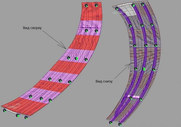
Completely cover plate our metal superstructure. General view:
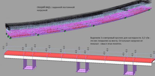
Next, we need to model all of the permanent external loads experienced by our constitution, and they are: the weight of the asphalt (as modeled load of asphalt - by clipping in the picture), the weight of the barrier fence, railing, the weight of the formwork that forms the reinforced concrete slab, well, and others. All loads are given in the form of forces applied to the rod or slab elements
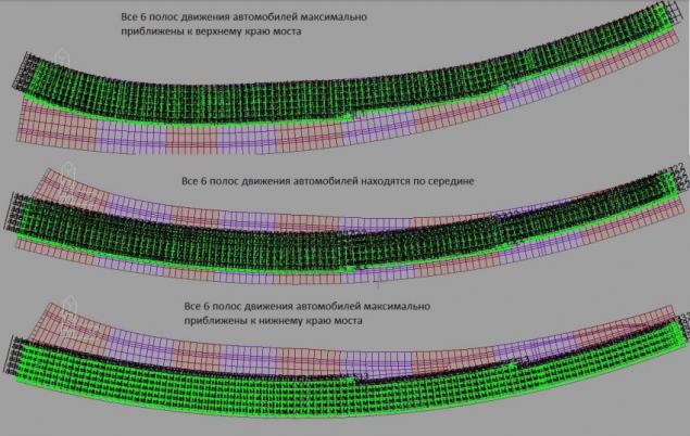
So, proceed to the next interesting point of design, you need to specify a temporary load, ie, stream of cars moving on the bridge. The rules and regulations have a standard (reference) vehicle, it is the benchmark load and span will be calculated. First things first, you need to decide how many lanes is the section of the highway, on the instructions - a 6 lanes. Consider all possible movement of cars to find the most unfavorable decision (all calculations are carried out on the most critical loads and disadvantage, which in principle can not happen - the so-called margin calculations)
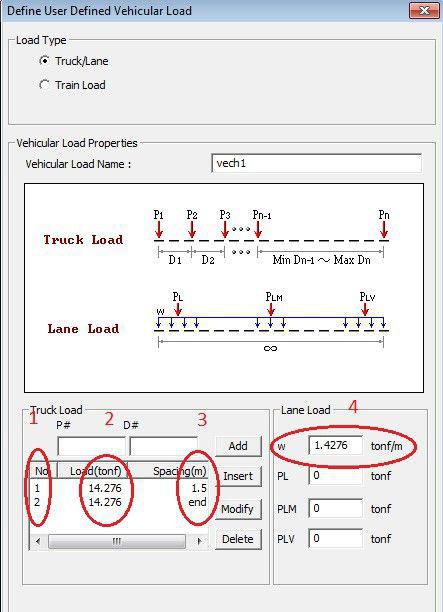
So, "rails" (or lanes) are given now to move the car on them, it is necessary to mathematical description:
1 Number of axles of the car (2 axes at the cars, each with 2 wheels, okay?)
2 load 1 axis (14, 276 tons - only one axis). Ie the mass of the reference vehicle will be equal to 28 552 tonnes ("a lot" - you might say. "Those are the rules," -Tell us .
3 The distance between the axles - 1.5 meters.
4 Uniform load on the flow of traffic (1 meter strip has to already 1, 4276 tons), the fact that each of the six bands mentioned above will be located only 1 such a "machine" (the trolley on the right) and the load on the vehicle stream (this is equivalent to, if you put the trolley reference each other across the bridge). There is also nothing about it, those are the rules.
Congratulations !!! There comes a moment of truth and we press the button "Calculation" The program itself puts the car in the most disadvantageous position, looking for various options of transport to bridge both along and across said ...... .... still believes ... again finds ... leave a smoke ... OD ... READY!
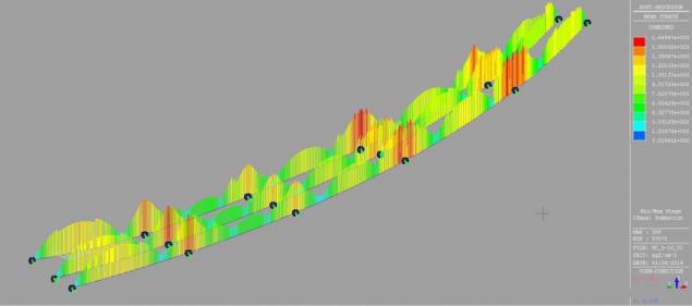
Getting to remember the purpose of our calculation - yeah, you need to find all the sections of metal boxes, or the main load-bearing elements of the bridge - span. Render the final voltage obtained in the calculation again remind, the program (and all similar software systems) nainevygodneyshee itself calculates the position of all loads.
Let's see how well distributed stresses in the main beam:
And while you watch, I will explain that stress - is a measure of internal forces resulting in a deformed body, under the influence of various factors. Roughly speaking, under the influence of external forces (machines, load on the asphalt, snow, etc.), the material is deformed, but each material has a deformation section, which has no adverse effect on the material. Each material that limit its. So that sense of constant iterations (see. P. 11) - a follow-up of critical stresses in the structure to ensure that emerging voltage does not exceed the maximum allowable stress, which is ready to sustain our steel bridge. By monitoring these stresses we will increase or decrease the thickness of the walls and belts (upper and lower sheets) in the design. You can also keep track of absolutely every element in the design, you can see at what time, and what position the load cell will suffer the most
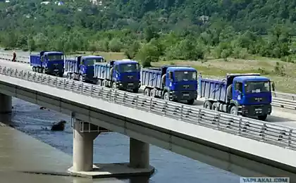
Total base calculation, I outlined to you, a little to introduce you to the design and calculation of bridges, those objects that you see every day on which you drive, who constantly repaired. As a bonus, I will put more merry estimated picture SIFCO well and a couple of photos of the result of painstaking design and analysis.
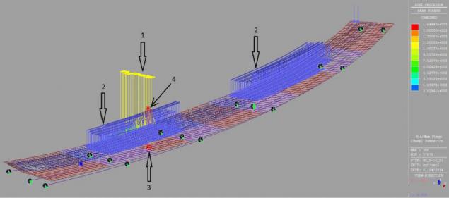
Let's look at the main element in the central beam in the middle of the second span, under any circumstances, as it will be the most loaded. Yeah, if you put them on carts 6 (1) (each yellow line represents the load on the wheel carts), and the flow of transport (2) of the six bands lie in the second and fourth bays. At this point (4) the maximum force occurs.
Well SIFCO that shows deformation and work span, visualization of points of maximum displacement of the superstructure elements under load. Of course, the scale is increased tenfold, to actually move and deformation are measured in millimeters. However, monitoring and visualization of large scale movements are used for illustrative purposes.
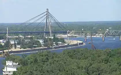
And this is the outcome of painstaking calculations, drawings, coordination at all levels:
More
Bottom View more
--img22--
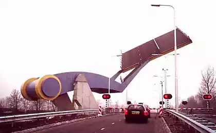
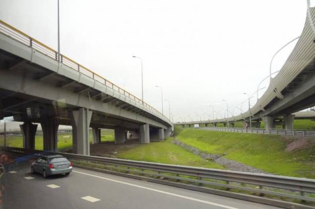
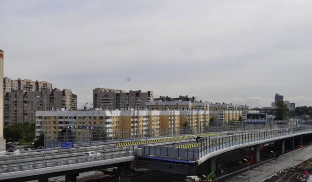
Well iposlednyaya picture as they see drivers with their warm and heated seats. This collapse, a brief review is completed.
--img23--
Source DUKUU
--img24--
Source:

First things first get itself the task of designing, in the job has been all surveys (geological, surveying, etc., are not always available, of course, but in this example were all data on the design). We need an electronic (format AUTOCad) version of the plan-drawing interchange coordinates and scale. This will be the most important basis for the design of our bridge. Red oval circled our site directly junction

Here's a closer outcome desired location. On the instructions necessary to design a 5-Flying-pass the continuous composite bridges. Produces about a breakdown (yellow line - is the main structural dimensions) bridge to span (several tens stage approvals and other paperwork). In this example, we see that the length of the span will be approximately equal (not carp about the size of the arc, and so on - it is simply illustrative example and an overview about how it all happens): 52, 83 M + 53, 34 + 62 m 22 M + 77, 02 + 62 m, 24 m. Total length of our future bridge will be equal to approximately 307.65 m, which refers to extra-curricular bridges.

Further there is a detailed breakdown of the final bridge to span structures and superstructures - blocks. In this case, it is clear that the basis of the span of the bridge are 3 "guide" or 3 main beams. Top view of the superstructure:

Let's look at a couple of cuts (6-6 and 7-7, for example) and that in fact it represents the construction of the superstructure of the bridge. As already mentioned above: the three main (supporting) element - the main beam. They are interconnected webs or cross beams for collaboration, cross beams at the edges - a console for the development dimension of the carriageway. Include all sizes construction along / across / on the plan. "Why have littered the horizon span?" - You might say. "First to Vodicka dripping" - I can tell. A second bridge is located on a bend on a small, but still bend, across the slope here is required for all regulations. The pillars on which rests (well, oil-oil, does not) span not shown here. The essence of the post - calculation of the superstructure of the bridge, not the supports (if interested, the theme was built on the calculation of support)

As a result, all sizes, dimensions and design details negotiated and approved by the customer. You can proceed to the calculation of the bridge itself, but rather the span of the bridge, just the part for which you, dear motorists vozite their ass from one bank to another. "But what is considered necessary, because everything has already drawn?" - You might say. I will answer you in a few steps:
1. On the basis of the construction of our bridge, we know that it consists of 3 metal boxes, which consist of vertical sheets (wall box), the upper and lower horizontal plates (upper and lower belt of the box, respectively). - Need to calculate the thickness, size and height of the sheet on the basis of all operating conditions (road category, traffic at the site, the climatic area in the end, what matters is not too small)
2. The reinforced concrete slab bridge (it is the one which then put asfaltik). She also suffers from external loads, it is necessary to calculate its interaction with the metal part of the superstructure, as well as its interaction with the wheel (automotive and extracurricular) load.
So, knowing all the dimensions, details, materials of construction of the superstructure can begin to integrate all the data to design programs of many different, I will focus on the complex, allows to model the three-dimensional structure of bridges, produce them in-depth consideration.
All such programs are based on the fundamental laws of physics, mechanics, strength of materials (Oo-oo-oo-oo-oo-oo, blonde, probably took a shiver when I remember the terrible things in the name of the university?).

We develop the basic design scheme of the bridge, it will be based on the use of plate-rod system. The program interface is hidden - semantic meaning do not see.
We start with the design "skeleton" beams span in the calculation program (those in the know - based on the calculation of the structural finite element). Each segment between red dot - an element of the main beam span. Black and green dots - a place bearing span to support (the program it looks like a travel ban construction at this point in a particular direction until).

Adding cross beams and brackets
Rigidly connecting the two special "fasteners" to work together (otherwise called - rigid insert). For clarity, I cut a piece of the span to have a general idea.

A general view of the entire core structure. Visualization points, limiting segments of elements removed, so the meat. But to understand the main beams, cross beams and brackets, can be rigid inserts. To illustrate the scale of the general structure:

Design scheme, consisting of bars, or finite elements ready. Now you need to describe each stem (element), to give it shape and material.
- For a description of the main beam, we use box section, wall thickness and assign zones. While all three beams principal throughout the length will be just that the cross-section (looking ahead to say that this is not the final version, but only the first iteration, then will the selection of cross-sections, depending on the results of the calculation, there may be any number as long as the selection It does not satisfy all the rules and regulations). Typically, in the first iteration (in other words - in a first approximation) the thickness of the wall sheets and belts are given based on experience.
-To Describe the cross-beams and I-beams console we take again ask-section, giving a wall thickness and a belt (as empirically appointed).
Well, and assign the material to our design described in the window of its characteristics, this example describes the characteristics of bridge steel 15HSND.

The most interesting stage. It is necessary to "dress" the cross sections on our rods. In other words - to designate the characteristics of the end elements of the cross-section and material. Dress, visualize:

The metal part of the superstructure is ready. Getting the design of reinforced concrete slabs. Assigns the thickness of the material (in this case - is a concrete grade B35 and piece by piece laid it on our metal. Note that those hard links, which connect the main beams and cross are also common components with a stove, it is all in order to model works together.

Completely cover plate our metal superstructure. General view:

Next, we need to model all of the permanent external loads experienced by our constitution, and they are: the weight of the asphalt (as modeled load of asphalt - by clipping in the picture), the weight of the barrier fence, railing, the weight of the formwork that forms the reinforced concrete slab, well, and others. All loads are given in the form of forces applied to the rod or slab elements

So, proceed to the next interesting point of design, you need to specify a temporary load, ie, stream of cars moving on the bridge. The rules and regulations have a standard (reference) vehicle, it is the benchmark load and span will be calculated. First things first, you need to decide how many lanes is the section of the highway, on the instructions - a 6 lanes. Consider all possible movement of cars to find the most unfavorable decision (all calculations are carried out on the most critical loads and disadvantage, which in principle can not happen - the so-called margin calculations)

So, "rails" (or lanes) are given now to move the car on them, it is necessary to mathematical description:
1 Number of axles of the car (2 axes at the cars, each with 2 wheels, okay?)
2 load 1 axis (14, 276 tons - only one axis). Ie the mass of the reference vehicle will be equal to 28 552 tonnes ("a lot" - you might say. "Those are the rules," -Tell us .
3 The distance between the axles - 1.5 meters.
4 Uniform load on the flow of traffic (1 meter strip has to already 1, 4276 tons), the fact that each of the six bands mentioned above will be located only 1 such a "machine" (the trolley on the right) and the load on the vehicle stream (this is equivalent to, if you put the trolley reference each other across the bridge). There is also nothing about it, those are the rules.

Congratulations !!! There comes a moment of truth and we press the button "Calculation" The program itself puts the car in the most disadvantageous position, looking for various options of transport to bridge both along and across said ...... .... still believes ... again finds ... leave a smoke ... OD ... READY!
Getting to remember the purpose of our calculation - yeah, you need to find all the sections of metal boxes, or the main load-bearing elements of the bridge - span. Render the final voltage obtained in the calculation again remind, the program (and all similar software systems) nainevygodneyshee itself calculates the position of all loads.
Let's see how well distributed stresses in the main beam:
And while you watch, I will explain that stress - is a measure of internal forces resulting in a deformed body, under the influence of various factors. Roughly speaking, under the influence of external forces (machines, load on the asphalt, snow, etc.), the material is deformed, but each material has a deformation section, which has no adverse effect on the material. Each material that limit its. So that sense of constant iterations (see. P. 11) - a follow-up of critical stresses in the structure to ensure that emerging voltage does not exceed the maximum allowable stress, which is ready to sustain our steel bridge. By monitoring these stresses we will increase or decrease the thickness of the walls and belts (upper and lower sheets) in the design. You can also keep track of absolutely every element in the design, you can see at what time, and what position the load cell will suffer the most

Total base calculation, I outlined to you, a little to introduce you to the design and calculation of bridges, those objects that you see every day on which you drive, who constantly repaired. As a bonus, I will put more merry estimated picture SIFCO well and a couple of photos of the result of painstaking design and analysis.
Let's look at the main element in the central beam in the middle of the second span, under any circumstances, as it will be the most loaded. Yeah, if you put them on carts 6 (1) (each yellow line represents the load on the wheel carts), and the flow of transport (2) of the six bands lie in the second and fourth bays. At this point (4) the maximum force occurs.

Well SIFCO that shows deformation and work span, visualization of points of maximum displacement of the superstructure elements under load. Of course, the scale is increased tenfold, to actually move and deformation are measured in millimeters. However, monitoring and visualization of large scale movements are used for illustrative purposes.

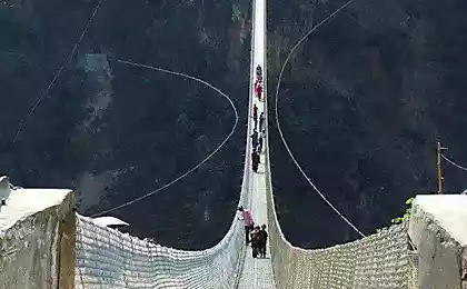
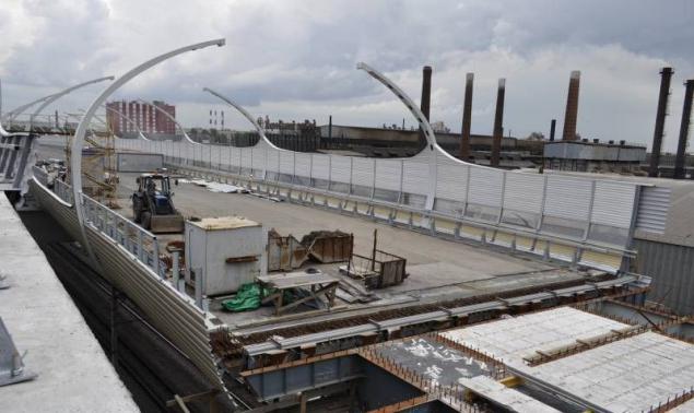
And this is the outcome of painstaking calculations, drawings, coordination at all levels:

More

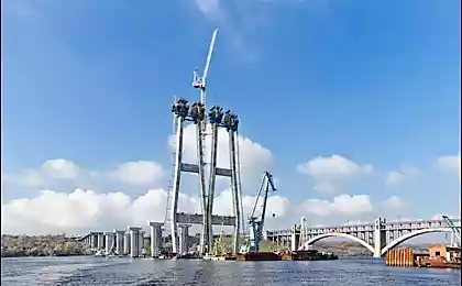
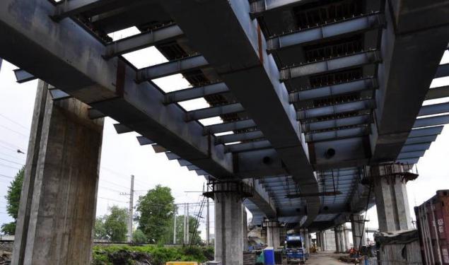
Bottom View more
--img22--
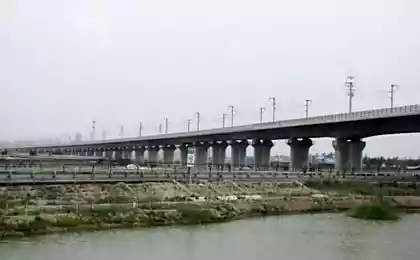
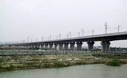
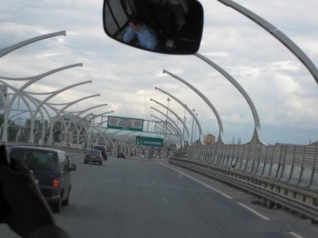
Well iposlednyaya picture as they see drivers with their warm and heated seats. This collapse, a brief review is completed.
--img23--
Source DUKUU
--img24--
Source: