Logic avtorobota from machine vision to control transmission

A.Zhukovsky, S.Usilin, V.Postnikov h6> Today we want to talk about the new project, which began just over a year ago at the department "cognitive technologies" MIPT.

It consists in creating a machine vision system, the robot - the vehicle ( Fig. 1 ), which is a real-time video stream should process to recognize the surrounding scene to detect objects and generate the manipulated variable, aimed at the solution of the problem.


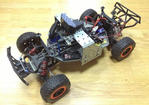
Figure. 1 h6> Here we are not trying to recreate the actual conditions of the road scene, eliminating all the charm of a small-size modeling.

For starters, simple examples, we would like to work out the basic architectural components of the system (base receiving the video stream and distributed processing on a combination of mini-computers and video cameras, as the prototype of System-on-a-Chip (SoC)), potentially useful for solving more complex problems.

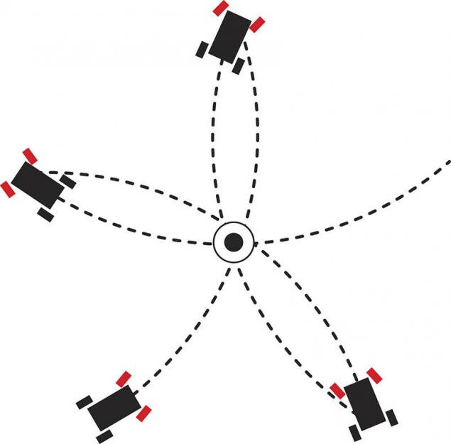
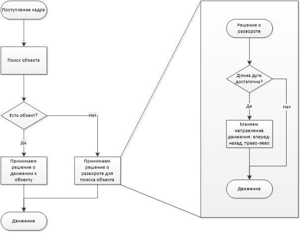
WE WILL taught the robot to move along the corridor and to detect simple objects, such as an orange traffic cone. The challenge was that he could drive up to the object and stop. And then decided to play with the ball. In the current version, if the ball is in the camera field of view, the robot detects the ball accelerates and pushes his bumper. If the ball leaves the field of view of the camera, the robot starts to look for him.


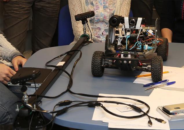
Video shot during a report on the fall conference of young scientists MIPT,
right in the corridor of the main building h6> Now we teach the robot to pass "snake" at the time. This exercise makes it possible to assess the quality management system and its progress from version to version. And compare with the quality of the manual control with the person.

Initially, our robot contained only the control computer, camera and, in fact, the chassis. This model is a sports utility vehicle Traxxas Slash 2wd made in 1:10. ( Fig. 2 , Fig. 3 )


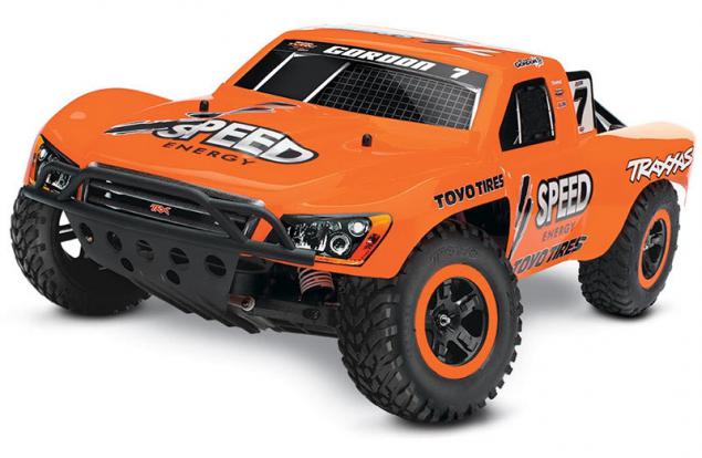
Figure. 2 Traxxas Slash 2wd h6> Controller chassis is made based on the Arduino nano, but in fact it only uses a microcontroller ATMega32.

A little later, we added a front diagram sonar to monitor the distance to the obstacle - simply put, the robot has not fought in the bumper corners and walls.


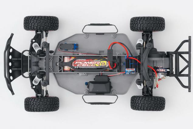
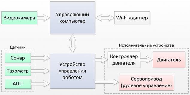
Figure. 3 Traxxas Slash 2wd h6> If the first version of the robot to broadcast video over HTTP back and generating control signals conducted on the desktop, then in the current version 2.0 (shown on video) the whole cycle is closed on board, with the main burden fell on the video processing on minicomputer Odroid U2. ( Fig. 4 -1 )

In addition to computer equipment in version 2.0 include:

  • the robot control unit (Fig. 4, -2);
  • Video Camera Logitech HD Pro C920 / Genius WideCam 1050 (can be used practically arbitrary webcam) (Fig. 4, 3);
  • Wi-Fi-adapter ASUS USB-N10 (Fig. 4, -4);
  • USB-hub (Fig. 4 -5)
  • sonar LV -MAXSONAR-EZ2 (Fig. 4 -6)


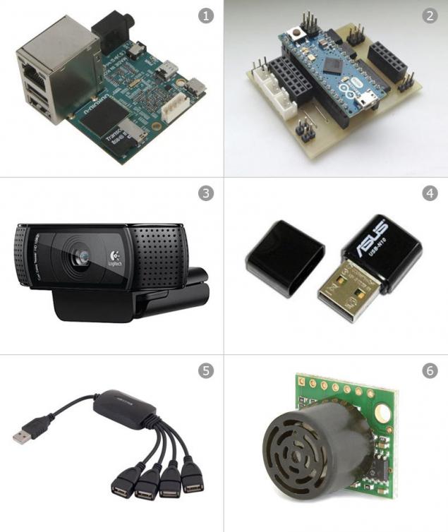
    Figure. 4 h6> to device features a robot control include:

    1. Implementation Team Manager computer
    2. the formation of Governors of the PWM signal,
  • management of the external load (7 channels);
processing signals from sensors < /:
sonars (8 channels), The Hall sensor, Battery voltage sensor (ADC); protection robot emergency stop on the frontal sonar, stop control signal is lost.


Figure. 5 Schematic of the robot h6> Now we collect the 3rd version. In her video capture system will include two professional cameras already IDS, the video signal from which (including the detection of objects) will be processed on separate minicomputers, in turn, connected to a central minicomputer producing the final scene recognition and the development of control actions.

It is also planned to put several sonars on the perimeter of the robot to more fully represent the environment to solve the problems of parking.

Further planned quite a lot of improvements, for example, we want to hang on the robot light equipment, like a real car, which of the details printed on the 3D-printer. It is necessary to simulate the movement of the vehicle in front to support a certain distance (in the case of motion in heavy traffic or traffic jam).

The first digression. I> h6> By the way, if you do something like that, immediately warns against using Chinese counterparts - the first version of the motor controller has been made on it, which resulted in a few weeks search for the causes of strange behavior of the motor - it turned out that the microcontroller of the "analog" closed the time, some of the inputs to the outputs. Maybe it's because we were lucky, but with the original Arduino such problems were noted.

The second digression. I> h6> Before creating the controller chassis, it appears that it is not known how and what to manage. Lack of official documentation on the control signals chassis components gave occasion to remember in physics labs and fiddle with the oscilloscope. In the end it turned out that it uses pulse-width modulation. In general, nothing complicated.

Third digression. I> h6> Somewhere in the interval between the detection of the problem and collecting the new controller was decided to abandon the circuit board, which was assembled the first controller, and therefore of naphthalene was taken "of the iron-printer" method of PCB layout. The result was very neat and cool.

Algorithm for robot behavior chasing a ball represented schematically in the figure below. It seems nothing incomprehensible in him. Is it necessary to say a few words about the reversal algorithm. This testing of the situation when the ball leaves the field of view of the robot. In fact, it exists only four possible to turn: forward right, front left, back right and back left. The robot remembers where he saw the ball for the last time and turns in this direction by complete analogy with the player, from a field of view which is missing the ball. He tends to turn in the direction where the ball flew.


For reversal, we apply the algorithm "star": drive, for example, first to the right and forward, then back to the left and receiving such an arc convex toward the common center point. This maneuver, reminds turn in a limited space, known to many by the traffic police exam ( Fig. 6 ).


Figure. 6 h6> If there is a deadlock related to the fact that the robot is stuck, for example, caught in the leg of a chair, program management identifies this situation due to discrepancies engine speed and the angle of rotation of the wheels. In this case, the robot tries to back, to make a maneuver by "star" and continue towards the goal.


Fourth digression. I> h6> When we were preparing for the conference of young scientists MIPT, then to gain the viewer's perception increased akkseleratsii parameter. As a result, the robot became more abut the obstacles, as the case detection scheme "jam" has ceased to operate properly - steel wheel slip. Moreover, at high speed the robot become increasingly overshoot the ball (as shown in the first video). So we had to solve the problem of optimal balancing between the processing speed of the video stream, the movement of the robot and make a decision. In terms of complexity, she reminded the problem of addiction to the old Soviet-made car with a manual, type "Moskvich" or "Lada" each of which was on - its adjusted clutch and ignition. Who experienced this, he realizes that it takes some time to adjust to catch the balance between the clutch and the gas pedal to the car accelerated smoothly.


Figure. 7 Algorithm for robot behavior chasing a ball h6> The third version of the robot (which is almost complete), we switched to using "professional" video camera and lens.


Figure. 8 h6> In parallel experiments we carried out the installation of cameras on rails that are mounted on rails full-size car ( Fig. 8 ). This will reproduce the real geometry and the conditions of the road scene.

Learn more about the new version of the robot, we plan to tell in the next article.


Source: habrahabr.ru/company/cognitive/blog/226417/

Tags

See also

New and interesting