The screw design of the wind turbine
 Bashny.Net
Wind power today is an actively developing branch. But the use of wind energy is associated with certain difficulties, in particular weak and inconsistent the wind. The following screw design allows to increase the efficiency of the wind turbine.
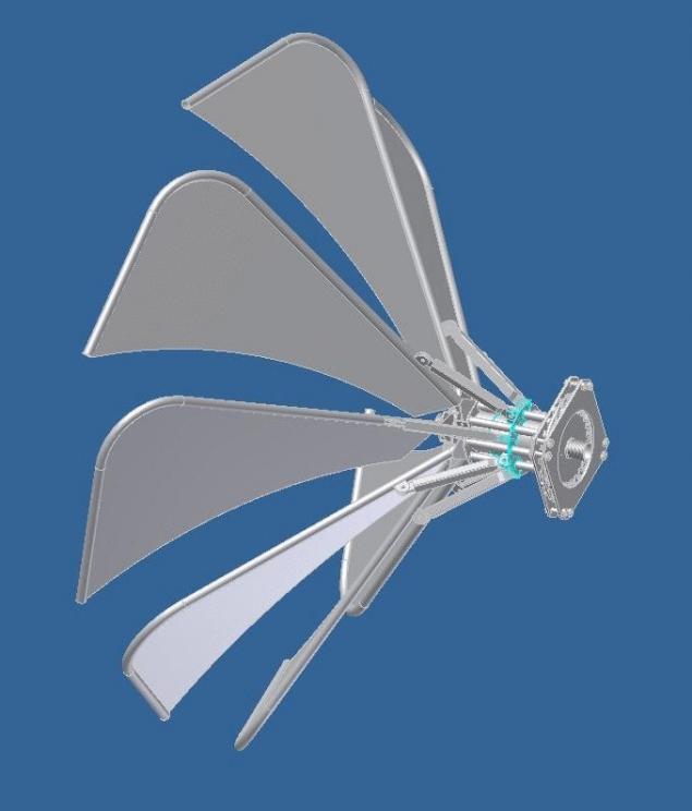
Today there are many designs of propellers of wind turbines. This design is an improved version of this set and has higher performance in terms of use with a weak and unstable wind.
All existing lot can be divided into two types. The first type uses the lifting power of the wind (a windmill with a horizontal axis of rotation), the second type uses the force of the flow (the wind turbine with vertical axis of rotation). This design combines both the possibilities of using wind power.
Let's take a closer look at this design.
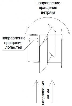
The figure above shows the design of the wind turbine with vertical axis of rotation. The blades rotate around its axis in the opposite direction of rotation of the windmill.
Wind turbine it is necessary to strictly rely on the wind direction.
The figure below shows the structure of the wind turbine (top view).
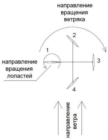
During operation of the wind turbine blades rotate around its axis in the opposite direction of rotation of the wind turbine in such a way that during the rotation of the turbine 360 degrees, the blade will rotate 180 degrees.
Observing such proportion of the rotation, we finally get the blade moving in the direction of the wind perpendicular to the flow of the wind. (1)
On its return stroke when the blade moves against the wind, she turned to the stream edge and has the least drag. (3)
In the intermediate state, the blade angled to the direction of movement of the wind, and it operates the lift vector coincides with the vector rotation of the wind turbine. (2,4)
Let's take a closer look at the forces acting on the blades of the wind turbine.

We believe that the windmill is spinning with the speed of wind or close to it. The blade is in position 1, located perpendicular to the flow of the wind and moves with the speed of the wind, it does no work, its efficiency is equal to zero. In position 2-3 the blade moving in the direction of the wind starts to shift perpendicular to the flow of the wind and the speed of rotation of the windmill and wind speed of the incoming flow hits the edge of the blade, flowing around it and creates lift vector which is directed in the direction of rotation of the wind turbine. Arrows, size arrows conditionally showed an increase in the lift force of the wind. In the 4-position blade slightly moves in the direction of the wind, its main movement perpendicular to the flow, and given the speed of the wind turbine and the wind speed of the incoming flow hits the edge of the blade, flowing around it and creates lift vector which is directed in the direction of rotation of the wind turbine. In the 5-position blade moves perpendicular to the flow, as it occurs in wind turbines with horizontal axis of rotation, and it is the same strength as them. In the position 6-7-8 blade not only moves perpendicular to the flow, but starts to move towards him. Therefore, the lifting force of the wind increases, but the vector it is now gradually deflected in the direction of the direction of rotation of the wind turbine. Indicated by the arrows. In regulation 9 of the blade facing the wind squarely and moves towards him with the same speed. Therefore, the lifting force is 2 times larger, but is directed perpendicular to the direction of movement of the wind turbine. Going through a conventional zero, the lifting force changes its direction to the opposite, preserving the value. In the position 10-11-12 blade gradually decelerates the movement towards the stream and increases the motion perpendicular to it. Therefore, the vector of the lift force is reduced, but the vector direction is aligned and gradually begins to coincide with the direction of rotation of the wind turbine. I want to note the position of the blade remains optimal for the incident flow, which wraps around it and the stall does not occur. In position 13 the blade is moving perpendicular to the flow, as it occurs in wind turbines with horizontal axis of rotation, and it is the same power as the classical windmill with a horizontal axis of rotation. In the position 14-15-16 blade gradually slows its movement perpendicular to the wind flow and increases the motion in the direction of the wind. Lifting force of the wind gradually reduced. Vector lifting force coincides with the direction of rotation of the wind turbine. As the rotational speed of the turbine is equal or close to the speed of the wind, we cannot obtain any benefit from the force of the flow. But in a static position when the windmill is stopped, the ability of the design to use the power of flow is a huge plus. This gives the design a high starting threshold at low wind speed, allows to push the design until the blade will Orient relative to the incoming flow, and engages the lifting force of the wind.
For comparison, consider the Cup anemometer. The airflow presses on the left and right side of the anemometer is the same, but due to the fact that on the one hand, the Cup is turned to the flow convex side and concave on the other, creates a difference in pressure on left and right side. Design turns. This difference is 5-10%. In my design the blade in position 1, the rotated plane to the flow, as in position 9 by an edge. With this arrangement of the blades the pressure difference on the left and the right half will be much more than the Cup anemometer. Hence the conclusion: the starting threshold of the structure above the starting threshold of traditional wind turbines with vertical axis of rotation, and of course horizontal also.
The design has drawbacks: in particular, the front and the rear of the windmill is most fully uses the lifting power of the wind, but on the flanks the lifting force of the wind or tends to zero or the vector lifting force of the wind deflected from the direction of rotation of the wind turbine.
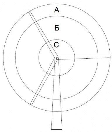
For comparison, consider the classic windmill with a horizontal axis of rotation. Let's neaten divide the surface into three areas: A, B, C. In area A blade moves faster than the speed of the wind and no work is done, and only creates an unpleasant low frequency noise. In region B, the blade moves with the wind speed and produces maximum work. In a region where the blade moves much slower wind speed, and consequently produces less work. In view of the specific design has large size and weight at the base of the blade, which leads to excessive sail and inertia of the wind turbine. Of the above it is seen that the blade of the wind turbine with a horizontal axis of rotation running in fragments. In my design the blade to work across its surface and, if you remember the theory, much closer to the ideal. The perfect wind turbine has an infinitely long and infinitely thin blades.
Let's take a closer look at the device of our design. At first glance it seems that the design of the wind turbine is quite complex and requires strict orientation towards the wind, makes demands of rotation of the blades with a given proportion, but it is not.
Consider one of variants of implementation of the design with specified parameters.
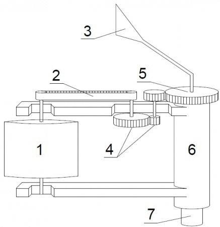
The picture above shows a schematic diagram of one shoulder of the wind turbine:
1. The blade of the wind turbine.
2. Toothed belt (timing belt) for transmitting rotation from the gearbox to the blades.
3. The element of orientation to the wind (weather vane, the tail).
4. Reducer.
5. Gear the orientation of the wind turbine in the wind.
6. The base of the wind turbine.
7. The mast on which is fixed a wind turbine.
A wind generator mounted on the mast 7 through the movable coupling (bearing) and rotates freely around its axis. The required ratio of rotation and direction of rotation of the wind turbine and of the blades is implemented via the gear mechanism 4 and is transmitted to the blade 1 by the strap 2. During operation of the wind turbine blades rotate around its axis in the opposite direction of rotation of the wind turbine (wind turbine rotates clockwise, the blade rotates counterclockwise) in such a way that during the rotation of the turbine 360 degrees, the blade will rotate 180 degrees. The direction of the wind turbine relative to the wind is determined by the position of the blades, which in turn depends on the gear of the orientation of the wind turbine in the wind 5. Gear 5 is fixed to the mast 7 through the movable coupling (bearing) and rotates freely around its axis. The position of the gear 5 is determined by the vane 3 (tail) which is rigidly fixed to the gear 5 and rotates it around the axis depending on the wind direction. Thus we see that for the organization the desired rotation of the blades is quite simple mechanism of the gearbox 4 and belt 2, which are pretty simple parts and can not increase the cost of the wind turbine. To Orient the wind turbine in the wind there is no need to rotate the entire structure as a wind turbine with a horizontal axis of rotation, it is sufficient to rotate the gear wheel 5, with which you can easily cope vane 3 without additional energy consumption.
A wind turbine and a small amount of the vane blades can easily cope with the task orientation of the wind turbine in the wind direction, however, with the increasing size of wind turbines and number of blades on the gear 5 (gear orientation of the wind turbine in the wind) there will be significant torque which will rotate the gear 5 in the direction of rotation of the wind turbine. The vane will oppose this force and return the gear to its original state, which is optimal for proper orientation of the wind turbine in the wind direction. The interaction of these oppositely directed forces will be rocking the gear 5, which will be transmitted via a gearbox 4 and belt 2, the blade 1, leading to unnecessary vibration. In order to prevent the unwanted vibration, it is necessary to replace the vane on the other design.
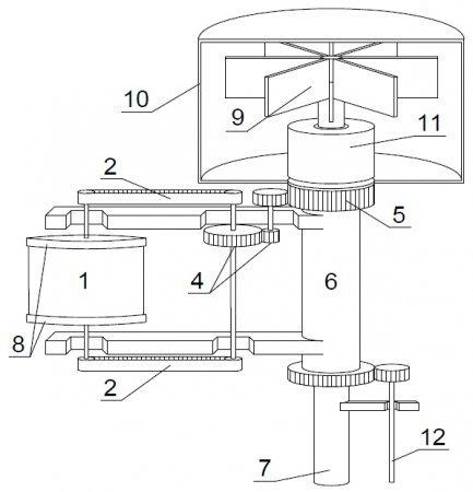
The picture above is a conventional image of the design of the wind turbine, which system of orientation in the wind consists of a rotating impeller 9, the rotary casing 10, and of the reduction gearing 11, which transmits torque to the gear 5.
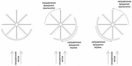
Consider the principle of this system of orientation. In the above figure on the left schematically shows the impeller and the screen that seperates the wheel from the wind. In this position, the impeller is at rest. When the wind direction changes, the screen doesnt push the impeller completely and the flow of the wind pushing on the uncovered screen, the blades of the impeller, leading them in motion. The impeller 9 rotates, transmitting this rotation through a reduction gear 11, the gear 5, which are fixed to the screen 10. The screen rotates in the same direction as the impeller but with the specified gear deceleration and closes the impeller from the flow of the wind. Whereby the impeller stops. When the wind direction changes in the opposite direction, everything is exactly the same, only the impeller is spinning in the other direction and the screen, turning in the direction of rotation of the impeller, closes it. Screen size affects the sensitivity of the design. If the screen size is a quarter of the circumference, the design becomes more sensitive to the change of wind direction.
The application of the reducer enables us more clearly to fix the position of the gears 5 and avoids possible rocking and unnecessary vibration. On the other hand less opposition to the rotation of impeller makes the design more sensitive to the slightest change in the wind direction. The more the reduction factor of the reducer, the greater the turning force keeps the gear 5 and higher the sensitivity of the design to changes in wind direction. But a large reduction factor increases the time of processing of changing the direction of the wind, which is undesirable in conditions of frequent changes of wind direction.
A compromise between the rigidity of the position of the gear 5, the size of the impeller 9 and the screen 10, the sensitivity of the design to changes in the wind direction, and time of processing of rotation necessary to establish experimentally, taking into account peculiarities of operation in specific conditions.
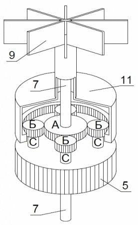
Consider reducer design detail. The figure above illustrates: the impeller 9, a gear in the section 11 and the gear 5 (gear orientation of the wind turbine in the wind). The impeller 9 is rigidly fixed on the gear housing 11 and makes a single whole with it. The whole structure is attached to the mast 7 through the bearing and rotates freely around the mast. Gear And rigidly fixed to the mast 7 and does not rotate relative to the mast. Four gears B are fixed to the axles through the bearings and freely rotate on these axes. Axis rigidly mounted in the gear 5. Gear 5 is fixed to the mast 7 through the bearing and rotates freely around the mast.
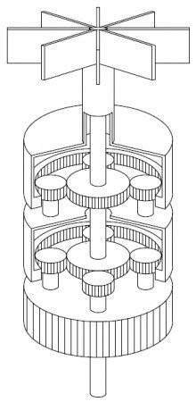
The rotating impeller transmits torque to the gear housing 11, which in turn drives gear B. Gear B move around the gear and transmit this movement through the axis of the gear 5, which determines the position of the blades of the wind turbine relative to the wind. To increase the reduction factor of the reducer you can use multiple segments, as shown in the figure below.
For the design of the wind turbine it is possible to use the electronic system orientation to the wind. To do this, remove the screen and the impeller. In place of the impeller the motor is fitted, which is controlled by the electronic circuit of orientation in the direction of the wind. This scheme of orientation makes it possible to remotely control the position of the blades. If necessary, remove the wind turbine from the wind, thus stopping it for maintenance, connection and disconnection equipment, etc.
Unlike wind turbines with a horizontal axis of rotation, where the driven equipment is high above the ground, this design of wind generator has a distinct advantage. The design of the wind generator allows you to easily transmit torque down to the base of the mast by a shaft 12. This is a significant advantage if the driven equipment has a large weight and dimensions and can not be raised high above the ground.
A windmill uses the lifting power of the wind as a driving force, but implements it through different trajectories of the blades, in comparison with the classical windmill with a horizontal axis of rotation. To use the power of the flow structure can only be at the start, which gives it high starting threshold. Design will not rotate faster than wind speed, and blade, located perpendicular to the flow, will not slow down rotation. Let's take a closer look at how the windmill.
If the design rotates in the wind, its blades located to the flow is strictly parallel, the flow wraps around the blade evenly on both sides and the lifting force does not occur. If the rotation of the windmill behind the wind speed at a certain angle, the free stream pressure on the blade with a positive angle of attack and generates lifting force of the wind. The windmill will seek to achieve the wind speed, but the closer the speed of the wind turbine to the wind speed, the lower the angle of attack of the incoming flow, and therefore the lifting force. If we load the windmill, trying to slow down it, the angle of attack will grow, and consequently will increase the lifting force of the wind. The rotational speed of the turbine will not fall, but the torque will increase. The wind turbine controls the angle of rotation of the blades depending on wind speed and remove power. If we draw an analogy, a classic windmill with a horizontal axis of rotation should be able to change the angle of rotation and jamming of the blade depending on wind speed in each moment of time. These blades are very difficult to do.
If you compare the design with simple horizontal wind turbine, it is of course much more difficult. But it is a necessary complexity to the design in order to adapt it to our conditions. I live in Krasnodar. The annual average wind load we — 6 m/s, the difference of speeds from dead calm to hurricane force gusts with frequent changes in wind direction. Such conditions almost in the entire territory of Russia. In such circumstances, classical windmill with a horizontal axis of rotation to operate efficiently will not. It is necessary to complicate the design, making turning vanes, to improve the system orientation to the wind (to avoid buildup). That is, we have to complicate the design to improve its efficiency. If my windmill will easily cope with the task of regulating the angle of attack depending on the shooting load and wind speed, with a classic horizontal windmill is not so simple. Making the rotary blade, we will be forced to abandon the wedge angles of the blade, it is necessary to make the blade straight, and it will worsen the aerodynamics of the rotor. Rotate the entire wind turbine together with a generator is much harder than turning the gear 5 in my design (gear orientation of the wind turbine in the wind).
The main advantage to my design over the classic horizontal wind turbine is a large torque when the speed of movement of the blades with wind speed. High starting threshold. Simplicity of orientation in the direction of the wind.
Classic horizontal wind turbine has a very high speed (can reach up to about 300. second), but should make it to the load as the rotation speed drops sharply.
How to conduct a numerical comparison of the received power, I don't know if you can tell me.
The wind turbine should be considered as a set: screw plus the payload, which screw pulls. And coordination of the screw with the load — a very important point. Consider the classic windmill with a horizontal axis of rotation. When the PTO speed of rotation begins to fall, but capacity increases to some value. We continue to increase the selection and then the power and the revs are falling. The task of the controller regulating the power to keep a constant maximum value, balancing on the peak. If the screw has a rotary blade, depending on speed of rotation of the blade change the angle of attack to increase the efficiency of the wind turbine. All of these adjustments are approximate, we do not know why fell speed. Changed the wind speed, the windmill handled by the PTO or some other reason. Then we must not forget that the wedge angles of the blade are calculated for a specific wind speed, and the screw can issue a maximum only if the wind corresponds to the parameters of the screw. And making the blades turning, are we even forced to abandon the wedge angles, which greatly impairs the aerodynamics of the rotor. Theoretical KIEV perfect screw with a horizontal axis of rotation N. E. Zhukovsky 0,593 G. H. Sabinin 0,683 real screw with practical, KIEV of 0.4, it is considered an excellent result. Roughly speaking, practical, KIEV is two-thirds theory. It's not because theory is bad, it is simply impossible to make a blade that will change the wedge angles and the angle of attack depending on wind speed. It is not clear how to adjust the angle of attack of the blade depending on the shooting power (why fell power, you must increase the angle of attack or just change the flow rate). Therefore, all horizontal screws work with the averaged parameters, wedge angles are calculated by the average wind speed, the angle of attack of the blades depending on the speed of rotation, without regard to remove the load, and so forth and so n.
With my design in another way, the turbine controls the angle of rotation of the blades depending on wind speed and remove power. If we overload the wind turbine, the angle of attack becomes too great, there is a disruption of flow from the blades and the rpm of the wind turbine drops below the wind speed. This is a clear boundary, we can load the wind turbine as long as the speed of rotation equal to the speed of the wind. The wind turbine controls the angle of rotation of the blades depending on wind speed and in output power and produces a maximum, while the rotation speed equal to the speed of the wind.
The speed of rotation of my wind turbine will never exceed the wind speed in contrast to wind turbines with a horizontal axis of rotation, the torque which it can give, greatly exceeds the torque of the wind turbine with a horizontal axis of rotation. And the rotation of the wind speed has its advantages. So when the diameter of the wind turbine 2 m in circumference of 6.28 is equal to m. That is, at a wind speed of 6m/s the windmill will make approximately one revolution per second. And hurricane winds of 25 m/s will make only 4 revolutions per second. This is a small speed and no prohibitive overload design experience will be, although this wind has a slate from the roof flies off. No need to compare with wind turbines that use the power of flow as a driving force, as they do maximal work when the blade is moving three times slower speed of the wind, and my design — when the blade is moving at wind speed. Therefore my design is three times more effective.
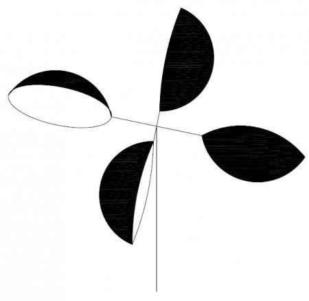
About the losses on the synchronization mechanism, the rotation of the blades. Let's take a closer look. In the absence of wind we hands untwisted the design of the shoulder, which is fixed to the blade and the mechanism of rotation of the blade. We will spend some energy on rotation of the structure, part of this energy spent on the rotation of the blade around its axis. But when the windmill is different. The blade is a driving design detail on the blade operates the lift of the wind. Consider the blade more. The blade is symmetrical about the chord, both faces of the blade equally rounded (as the blade is rotated to thread it with a single face, then the other). In runoff with the rounded end of the blade the flow will be broken, forming a low pressure area that will lead to the fact that the vector lifting force of the wind is shifted slightly backward relative to the center of symmetry of the blade. In short, the blade is located under some angle to the incident flow, will tend to turn parallel to the stream. There will be torque. If this is the suitcase the handle to attach off-center and slipping to the side, suitcase warps, heavier suitcase will not be a simple point of support does not coincide with the center of gravity. When the blade moves to the front relative to the incoming flow that occurs a warp effect coincides with the direction of rotation of the blade. When the rear of the arising twisting effect counteracts the rotation of the blade. These forces are equal, but oppositely directed, and must balance each other. But in practice, the blade moving along the front will receive more energy from the flow than the blade moving along the rear (it is as if in the shadow of the first, part of the energy flow is already given, and its impact on the blade weaker). Therefore, the result of the addition of these oppositely directed forces we will be left with a positive balance coinciding with the direction of rotation of the blade. The more the blade has a design, the greater the shading effect and the stronger will manifest the torque of the blade.
The now classic wind turbines with a horizontal axis of rotation used for the industrial production of electricity. This is because he has a high KIEV, simple design. But these windmills picky about the placement. It should be a platform with a strong constant wind. Such places a bit, mostly the coast of seas and oceans. To work in other circumstances, we have to complicate the design, giving it a new quality. Quiet (for the possibilities for accommodation near the place of residence), ease of orientation to the wind, high starting threshold, the resistance to hurricane-force gusts of wind.
My design has all these qualities. Her niche market is a small wind turbines placed on roofs or near buildings.
The basic idea of this design is to obtain a compact wind turbine that is able to work steadily in low and moderate winds. This wind load is almost the entire territory of Russia. This opens up design wide range of applications and huge market.
Source: alternativenergy.ru
Tags
See also
How to make incredible glass Gorilla glass
A system of accumulation and redistribution of energy for smart grid
Device Ingressure - your helper in the kitchen
Blackbird – the world's first metromobile
Sailing windmill: design analysis and examples of usage
New wind turbine carousel
The development of alternative energy in the private sector. The hard way to the customer
Energy tailwind
What should be the energy in the city — alternative sources of electricity