"Almost clever" warm floor on the Arduino from the sandbox
 Bashny.Net
My usual evening is sitting at the computer. Cold nights often have a desire to make my resting place more comfortable. Rather, periodically it was just cold feet. Ideas were different, up to purchase the USB heated Slippers. However, they all seemed to me ridiculous and was brushed aside. And once, looking through the YouTube channel of one of the lovers of the Arduino, I came across a video where it was told about the infrared film. Seeing this film, I knew immediately: "That's what I need!"
This project may be summarized as follows: I put a piece of infrared film under an additional layer of flooring, adding automatic control system using Arduino, a few sensors and VB.NET. Now, in order that and how it happened.
Disclaimer
I have been doing similar projects for several years, doing for myself. Do to do: the process for me is much more interesting than the final decision. Therefore, the process description and experiments is given below, with such detailed details. The use of items sometimes not really justified from a financial point of view — I understand that. Periodically I change something (in approach, in the elements), but certainly not going to go over a ready-made solution, as it will just be uninteresting.
Why "almost smart"? I wouldn't call the temperature measurement and relay control with a timer "smart." As for the future — have an idea to improve the control algorithm by adding a learning function. That's when this project will be called something else.
Why is this publication:
Deciding that before the action should be prepared, I went to the search engines to find more information and reviews. Comments hatred. Someone called the film an ideal heating element and said successfully heats the whole house, someone complained about the complete uselessness and claimed that it's "divorce". I decided to experiment, because I love new things.
The bundles are different:
For the experiment, I needed only a small piece of the "magic" of the film, so the main criterion for purchase was the price and the minimum complete set (without the thermostat and mounts).
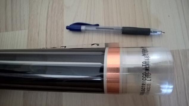
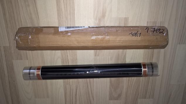
After checking prices, I settled on one sentence on AliExpress. The seller offered a 2 meter film width 50 cm for 8€, thermostat and mounts, however for the delivery of requested still the same. It was the most viable option. I made the order and waited for the parcel. After about 3 weeks the piece of film was already at my house.
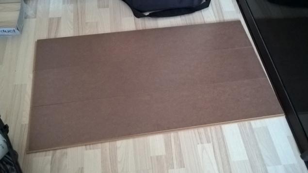
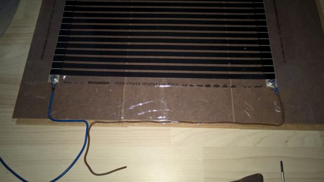
The first test After the film I got, I set myself the first task is to check whether it is working at all. To build the first prototype, I used three planks of the laminate remaining after a recent renovation.
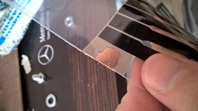
The Assembly process is simple: Cut film to desired length (I had about 100cm. theoretically, you can cut almost anywhere) Connected terminals (Here is an interesting point that the film is fully laminated on both sides. Even if the pin stripe looks like a big copper contact with one side of the film (see photo after receiving the parcel) – direct access to the contact is still there. If you use your terminal, you first need to aerate bawi's laminate)
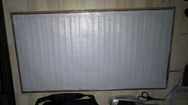
Taped film with Scotch tape to laminate Over the film cemented a layer of foil diplotriaena
Connect two wires to an ordinary plug socket for 220-250V
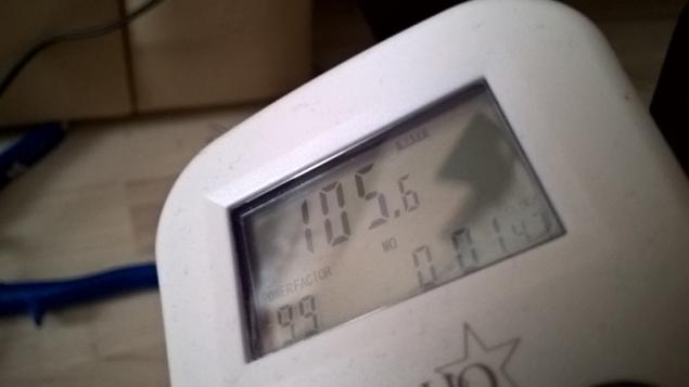
Included, measured consumption. The power consumed my a piece of tape was 105 Watts. If someone decides to use such a film can expect consumption as 200-210 Watts per square meter. Any "starting current" I have not seen, consumption is stable while you have the power not reduced. Of course, do not forget that the use of the thermostat will enter your coefficient estimates of consumption.
I stood up on the floor and waited for the effect. During the test, periodically switched to a regular floor, so as not to miss changes if the temperature will rise gradually. After a few minutes I felt a pleasant warmth coming from the floor. 15 minutes later, Paul had already roasted so that being on it was uncomfortable. The experiment could be considered successful, as it was clearly visible that the film can provide the necessary level of heat to provide for my needs.
The implementation of the "smart" part
While waiting for parcel in my head has developed a fairly clear picture of how to work my warm floor. As this is not my first project I decided to make maximum use of existing developments. In fact, to control the temperature of the floor I decided to apply the same algorithm and schema, and for automatic light control.
Compare the basic rules of algorithms:
The light We turn on the light, if the light level below the set We include a relay for a certain period of time, We turn on relays only if there is information from the motion sensor
Floor heating We turn on the heating, if the temperature is below the set We include a relay for a certain period of time, We turn on relays only if there is information from the motion sensor
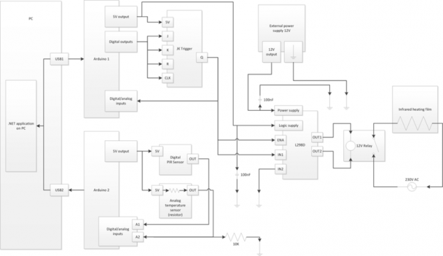
A kind of block diagram of the entire solution. Please do not judge strictly schema – drew it for publication was to understand the connection method and not bother finding the right icon.
Power relay floor
For power management use the combination of two circuit boards.
Module adds to the Arduino Nano:
The second card:
Pre-answer questions that might arise after getting acquainted with the boards.
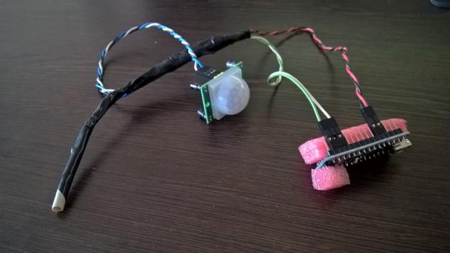
Temperature sensor tucked inside the braid CAT5 cable, as was the very small contact and touch seemed very fragile.
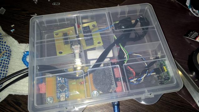
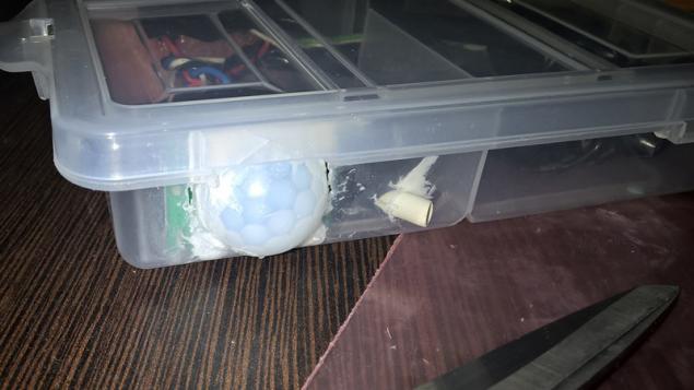
Case it was Assumed that all control elements will slide under the Desk on the floor. From this it followed that it will not be superfluous to do something similar to the case that the system cannot be easily damaged, accidentally hitting leg. Housing was used by a box designed for storing small items.
The housing Assembly
Slotted side holes for sensors
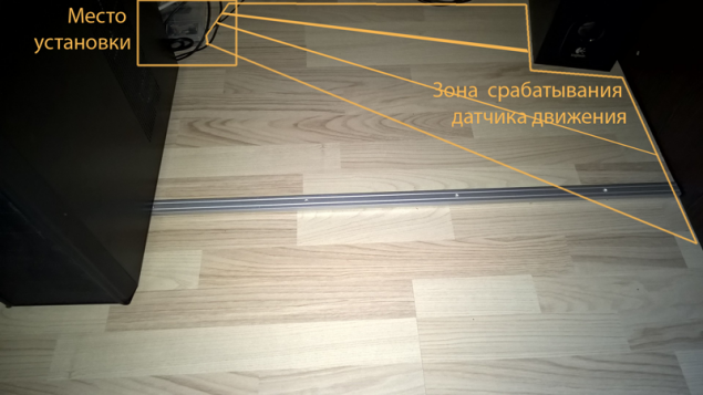
The ultimate option. Here's how it all looks after installation. The approximate area of the sensor motion is circled. Drew feels – when triggered, and when not.
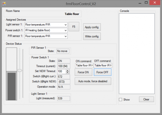
A screen shot of the window of the control program on the computer
(As mentioned, the control logic was copied from the system of light control, so on the form, you notice the inscription "Light" instead of "Temperature")
Conclusion
Both during testing and during operation of this solution assembled revealed some problems and nuances. Most of them related to the electrical and physical characteristics of the application circuits and their description is beyond the scope of this publication. Maybe later, I will describe the nuances in more detail in a separate post. Infrared film is an interesting material, and I can recommend it for use. Is it possible to use it as the only source of heat in the room and what will be the power consumption – I don't know.
In General, since the start of the project it has been several months. My "almost smart" warm floor works perfectly and serves its purpose 100%, though sometimes have to adjust the desired temperature. published by P. S. And remember, just changing your mind — together we change the world! ©
Source: geektimes.ru/post/259498/
This project may be summarized as follows: I put a piece of infrared film under an additional layer of flooring, adding automatic control system using Arduino, a few sensors and VB.NET. Now, in order that and how it happened.

Disclaimer
I have been doing similar projects for several years, doing for myself. Do to do: the process for me is much more interesting than the final decision. Therefore, the process description and experiments is given below, with such detailed details. The use of items sometimes not really justified from a financial point of view — I understand that. Periodically I change something (in approach, in the elements), but certainly not going to go over a ready-made solution, as it will just be uninteresting.
Why "almost smart"? I wouldn't call the temperature measurement and relay control with a timer "smart." As for the future — have an idea to improve the control algorithm by adding a learning function. That's when this project will be called something else.
Why is this publication:
- interesting to get constructive criticism/ideas
- to acquaint the community with infrared film
Deciding that before the action should be prepared, I went to the search engines to find more information and reviews. Comments hatred. Someone called the film an ideal heating element and said successfully heats the whole house, someone complained about the complete uselessness and claimed that it's "divorce". I decided to experiment, because I love new things.
The bundles are different:
- The width of the film (50, 80, 100cm)
- Length (2 meters) (where there was information that when the width of 50cm, the maximum allowable to use up to 6 meters of tape in one segment on one connection (data source))
- The presence of complete thermostat
- The presence of the supplied fasteners (alligator clips) to connect power to the film (judging by the comments is important, since some types of Chinese fasteners over time, weaken and deteriorate the contact up to complete disappearance)
For the experiment, I needed only a small piece of the "magic" of the film, so the main criterion for purchase was the price and the minimum complete set (without the thermostat and mounts).
After checking prices, I settled on one sentence on AliExpress. The seller offered a 2 meter film width 50 cm for 8€, thermostat and mounts, however for the delivery of requested still the same. It was the most viable option. I made the order and waited for the parcel. After about 3 weeks the piece of film was already at my house.

The first test After the film I got, I set myself the first task is to check whether it is working at all. To build the first prototype, I used three planks of the laminate remaining after a recent renovation.

The Assembly process is simple: Cut film to desired length (I had about 100cm. theoretically, you can cut almost anywhere) Connected terminals (Here is an interesting point that the film is fully laminated on both sides. Even if the pin stripe looks like a big copper contact with one side of the film (see photo after receiving the parcel) – direct access to the contact is still there. If you use your terminal, you first need to aerate bawi's laminate)


Taped film with Scotch tape to laminate Over the film cemented a layer of foil diplotriaena

Connect two wires to an ordinary plug socket for 220-250V
Included, measured consumption. The power consumed my a piece of tape was 105 Watts. If someone decides to use such a film can expect consumption as 200-210 Watts per square meter. Any "starting current" I have not seen, consumption is stable while you have the power not reduced. Of course, do not forget that the use of the thermostat will enter your coefficient estimates of consumption.

I stood up on the floor and waited for the effect. During the test, periodically switched to a regular floor, so as not to miss changes if the temperature will rise gradually. After a few minutes I felt a pleasant warmth coming from the floor. 15 minutes later, Paul had already roasted so that being on it was uncomfortable. The experiment could be considered successful, as it was clearly visible that the film can provide the necessary level of heat to provide for my needs.
The implementation of the "smart" part
While waiting for parcel in my head has developed a fairly clear picture of how to work my warm floor. As this is not my first project I decided to make maximum use of existing developments. In fact, to control the temperature of the floor I decided to apply the same algorithm and schema, and for automatic light control.
Compare the basic rules of algorithms:
The light We turn on the light, if the light level below the set We include a relay for a certain period of time, We turn on relays only if there is information from the motion sensor
Floor heating We turn on the heating, if the temperature is below the set We include a relay for a certain period of time, We turn on relays only if there is information from the motion sensor
A kind of block diagram of the entire solution. Please do not judge strictly schema – drew it for publication was to understand the connection method and not bother finding the right icon.

Power relay floor
For power management use the combination of two circuit boards.
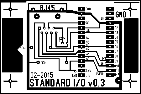
Module adds to the Arduino Nano:
- The attachment in my stand automatics (4 cross on the sides)
- RJ-45 ports for input/output (talking about the network not — I'm just using these connectors for switching)
- Input for 12V (if you use the plug-in Board)
- Two resistance of 10 ohms for connecting analog sensors

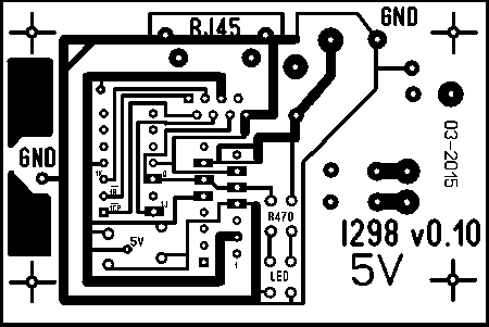
The second card:
- The attachment in my stand automatics (4 cross on the sides)
- Contains a JK flip-flop for memorizing the last command
- Bridge power L298D to pass a higher current to the relay coil
- Relay 5V or 12V depending on the version
- Multiple LEDs for status display

Pre-answer questions that might arise after getting acquainted with the boards.
- Why two boards? Implementation is copied from the existing light control where I feel so comfortable. If made from scratch – most likely charge would be one.
- Why a trigger? Indeed, for this solution I think it is unnecessary. Just in one of the previous versions of the system the controller was not connected to the bridge L298D constantly, and connected the multiplexer. Therefore there was a need to remember the set.
- Why L298D, if you can use optical connections? Again a legacy and a pack bought long ago for 3€ L298D.

Temperature sensor tucked inside the braid CAT5 cable, as was the very small contact and touch seemed very fragile.
Case it was Assumed that all control elements will slide under the Desk on the floor. From this it followed that it will not be superfluous to do something similar to the case that the system cannot be easily damaged, accidentally hitting leg. Housing was used by a box designed for storing small items.
The housing Assembly

Slotted side holes for sensors

The ultimate option. Here's how it all looks after installation. The approximate area of the sensor motion is circled. Drew feels – when triggered, and when not.

A screen shot of the window of the control program on the computer
(As mentioned, the control logic was copied from the system of light control, so on the form, you notice the inscription "Light" instead of "Temperature")

Conclusion
Both during testing and during operation of this solution assembled revealed some problems and nuances. Most of them related to the electrical and physical characteristics of the application circuits and their description is beyond the scope of this publication. Maybe later, I will describe the nuances in more detail in a separate post. Infrared film is an interesting material, and I can recommend it for use. Is it possible to use it as the only source of heat in the room and what will be the power consumption – I don't know.
In General, since the start of the project it has been several months. My "almost smart" warm floor works perfectly and serves its purpose 100%, though sometimes have to adjust the desired temperature. published by P. S. And remember, just changing your mind — together we change the world! ©
Source: geektimes.ru/post/259498/
Tags
See also
Google will spend $ 150 million to the racial composition of the company's employees has become more diverse
Barcelona eye Faktruma: 15 facts about barselontsev
How to escape from the heat in the apartment without air conditioning
Lukomorye
The differences between Russian and American schools
Geek House
Weapons Queen - exquisite
In this room it was located only a table and chair. What did this guy want to see!
At his disposal was just 8kV meters, but what he did ...
When kids hit parents