1638
Electric motors: what they are
In previous articles the principle of was considered synchronous and asynchronous motors, as well as instructions on how to manage them. But the kinds of motors, there are much more! And each of them has its own characteristics, scope and features. This article is a small overview of the different types of motors with pictures and examples of applications. Why put cleaner engines alone, and exhaust fan in the other? Which engines are in Segway? And what moving subway train?
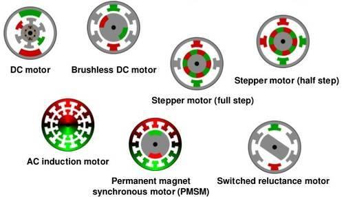
Each motor has certain identifying characteristics which determine its field of application in which it is most beneficial. Synchronous, asynchronous, DC, collector, brushless, valve-inductor, stepper ... Why, in the case of internal combustion engines, not to invent a couple of types, bring them to perfection and to put them, and only them in all applications? Let's go through all types of electric motors, and in the end will discuss why so many of them and what the engine "the best».
DC motor (DPT)
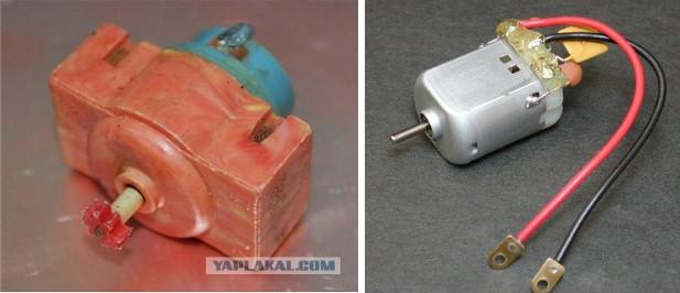
With this engine, all should be familiar since childhood, because it is this type of engine is in the majority of old toys. Battery, two wires to the contacts and the familiar sound of the buzz that encourages further engineering feats. All is not it do? Hopefully. Otherwise, this article is not likely to be of interest to you. Within such a motor mounted on the shaft pin assembly - collector switching the rotor winding, depending on the rotor position. Constant current supplied to the motor, one proceeds along the then other parts of the coil, creating torque. By the way, without going too far, after all, must have wondered - what the yellow stuff stood on the DBT some of the toys directly to the contacts (as pictured above)? This capacitor - when working collector of switching power consumption impulse, the voltage can also change abruptly, due to which the engine produces a lot of noise. They are especially hampered when the DPT is installed in remote control toys. Capacitors are quenched just high frequency ripple and, consequently, the interference is removed.
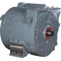
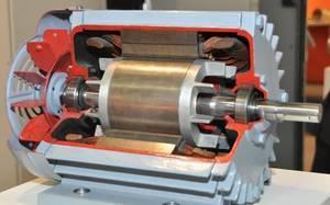
DC motors are a very small size ( "vibration" in the phone), and quite a lot - typically up to megawatts. For example, in the photo below shows a traction motor of an electric power 810kVt and 1500V voltage.
Why not make stronger DPT? The main problem of the DPT, DPT and in particular high-power - a collector node. Sliding contact in itself is not a very good idea, and the sliding contact on kilovolts kA and - even more so. Therefore, the collector assembly design for powerful DPT - an art, and to make a reliable collector becomes too difficult to power up megawatts.
In the consumer as DPT is good for its simplicity in terms of manageability. It is directly proportional to the armature current and speed (at least in idling) is directly proportional to the applied voltage. Therefore, until the advent of microcontrollers, power electronics and variable frequency AC drive is the DPT was the most popular motor for applications where the need to adjust the speed or time.
Also to be mentioned as it is formed in the DPT magnetic flux field, which interacts with the armature (rotor) and due to this there is the torque. This stream can be done in two ways: permanent magnet and field winding. In smaller engines often give permanent magnets in large - field winding. The winding drive - this is another control channel. With increasing excitation coil current its magnetic flux increases. This flux is included in the formula of torque, and the formula EMF. The higher the excitation magnetic flux, the higher the developed torque with the same armature current. But the higher the machine EMF, and means at the same voltage supply speed idling of the engine is lower. But if you reduce the magnetic flux, that at the same supply voltage idle speed will be higher going into infinity with a decrease in the flow of excitation to zero. This is a very important property of DBT. In general, I strongly advise to study equation DPT - they are simple, linear, but can be extended to all motors - similar processes elsewhere
.
Universal commutator motor
Ironically, it is the most common in the motor home, the name of which the least is known. Why did it happen? Its construction and features are the same as in a DC motor, so the mention of it in the textbooks of the drive is usually placed at the very end of the chapter about the DPT. This association collector = DPT so firmly sits in the head, that not everyone comes to mind is that the DC motor, which is present in the title, "DC", it is theoretically possible to include in the AC network. Let's see.
How to change the direction of rotation of a DC motor? It is known to all, it is necessary to change the polarity of the armature. And yet? And, you can change the polarity of the field supply, if the excitation is done winding, and not the magnets. And if the polarity change and armature windings and excitation? That's right, the direction of rotation does not change. So what are we waiting for? We connect the armature winding and the excitation in series or parallel, to the same polarity changed here and there, and then inserted into a single-phase AC power! Done, the engine will spin. There is only one small bar, which must be done: because by the excitation coil flows alternating current, its magnetic circuit, in contrast to the true DPT, it is necessary to produce a laminated to reduce eddy current losses. And so we got the so-called "universal commutator motor", which by design is a subspecies of the DPT, but ... works great as AC and DC.
This type of engine most widely distributed in household appliances, where the need to adjust the speed: drills, washing machine (not a "direct drive"), vacuum cleaners, etc. Why is it so popular? Because of their ease regulation. As with the DPT, it is possible to adjust the voltage level, which is a triac (bidirectional thyristor) for AC. control circuit can be so simple that it is placed, for example, directly into the "trigger" of the power and requires no microcontroller or PWM, no rotor position sensor.
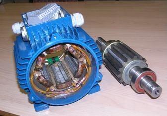
Asynchronous motor
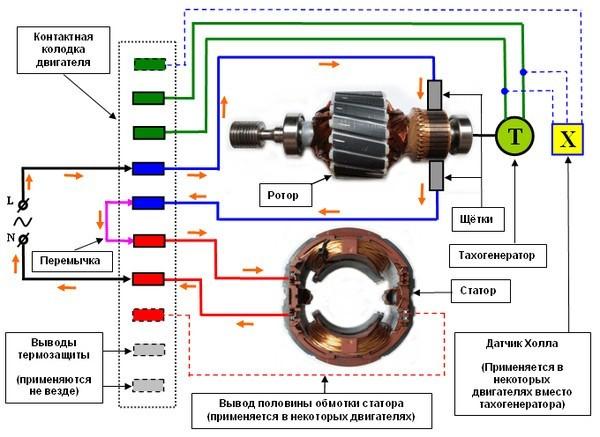
Even more common than the commutator motor is an induction motor. Only it is mainly distributed in the industry - where there is a three-phase network. About how it works written separate article. In short, its stator - a distributed two-phase or three-phase (polyphase less) coil. It is connected to an AC voltage source, and generates a rotating magnetic field. The rotor can be thought of as a copper or aluminum cylinder, inside which is a magnetic iron. By explicitly rotor voltage is applied, but it is induced there by the alternating field of the stator (so the engine in the English language is called induction). Emerging eddy currents in the shorted rotor interacting with the stator field, resulting in a torque.
Why asynchronous motor is so popular? It does not have sliding contact, like a commutator motor, and therefore it is more reliable and requires less maintenance. In addition, this engine can be started by AC "direct start" - you can turn the switch "on the network", with the result that the engine starts (with high inrush currents of 5-7 fold, but acceptable). DPT relatively high power so can not be enabled from the start-up current collector Pohorje. Also asynchronous drive, as opposed to the DPT, you can do much more power - tens of megawatts, also due to the absence collector. In this induction motor is relatively simple and cheap.
The induction motor is used in everyday life: In devices where not necessary to adjust the speed. Most often, the so-called "condensing" engines, or what is the same, "single-phase" asinhronniki. Although in reality from the perspective of the motor correct to speak of "two-phase", just one phase of the motor is connected directly to the network, and the second through the condenser. Making a phase shift capacitor to the second voltage winding that creates an elliptical rotating magnetic field. Typically, these engines are used in exhaust fan, refrigerator, small pumps, etc.
Less induction motor compared with DBT is that it is difficult to regulate. Asynchronous motor - is the AC motor. If AC motor simply lower the voltage without lowering the frequency, it will reduce the speed of a few, yes. But it will increase the so-called slippage (delay speed from the frequency of the stator field) will increase losses in the rotor, which is why it can overheat and burn. You can represent it to myself as a speed control car movement clutch exclusively by submitting full throttle and turning the fourth gear. To properly adjust the speed of an induction motor is proportional to the need to adjust both the frequency and voltage. And best of all, and to organize a vector control, as described in more detail in a previous article . But for this you need a frequency converter - a device with the inverter, the microcontroller, sensors, etc. Before the era of power semiconductor electronics and microprocessor technology (the last century) frequency regulation was exotic - it was nothing to do. But today Adjustable asynchronous electric drive based on the frequency converter - this is the standard de facto
.
The synchronous motor
About the principle of the synchronous motor also was a separate article . Synchronous drives can be several sub - magnets (PMSM) and without (with the field winding and the slip ring), with sinusoidal or trapezoidal EMF (brushless DC motors, BLDC). This may also include some of the stepper motors. It was used as a generator to the era of power semiconductor electronics lot of synchronous machines (almost all generators of power plants - synchronous machines), as well as a powerful drive for any serious loads in industry
.
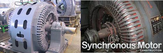
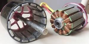
All of these machines were made with slip rings (you can see in the photo), a permanent-magnet in such capacities speech, of course, does not go. At the same time the synchronous motor, unlike asynchronous, start with big problems. If you include a powerful synchronous machine directly to the three-phase network, then all will be bad. Since the synchronous machine, it must rotate strictly with the network frequency. But during 1/50 second rotor, of course, accelerate from zero to mains frequency will not have time, and so it will be easy to twitch back and forth, as will the time alternating. This is called "synchronous motor is not logged-in". Therefore, in real synchronous machines used asynchronous start - do within synchronous machine small asynchronous starting coil and the short-circuited field winding, simulating "squirrel cage" asinhronnika to disperse the car to a frequency approximately equal to the rotating field frequency, and only then switched direct current stimulation and machine pulled into synchronism.
And if the induction motor to adjust the frequency of the rotor without changing the frequency of the field in any way we can, then the synchronous motor can not be in any way. He or spinning a part of the field, or falls out of synchronism and stops with disgusting transients. Moreover, the synchronous motor has magnets without contact rings - sliding contact to transfer energy to the excitation winding in the rotor. In terms of complexity, it is certainly not a collector of DPT, but still would have been better without sliding contact. That is why in the industry for irregular load is used mainly less capricious asynchronous drive.
But that all changed with the advent of power semiconductor electronics and microcontrollers. They are allowed to form for a synchronous machine any desired frequency of the field, tied by the provisions of the motor rotor sensor: organize valve engine operation (avtokommutatsiyu) or vector control. At the same characteristics of the drive entirely (synchronous machine + inverter) have turned out as they are obtained from the DC motor: synchronous motors are played in very different colors. Therefore, starting somewhere in 2000 started the "boom" of synchronous motors with permanent magnets. At first, they gingerly get out in the cooler fan as small BLDC motors, then got to the model aircraft then climbed into the washing machine as a direct drive in electric traction (Segway, Toyota Prius, and the like), are increasingly displacing classic in such problems commutator motor. Today, synchronous motors with permanent magnets grab more and more applications and run by leaps and bounds. And all this - thanks to electronics. But what is the best synchronous motor asynchronous when compared converter set + engine? And the worst? This issue will be considered at the end of the article, now let's go further in several types of electric motors.
Inductor-valve engine with self-excitation (VIEW ST, SRM)
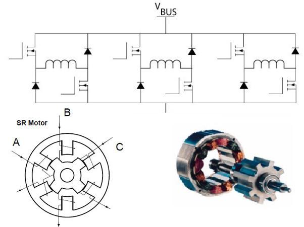
He has many names. Usually, it briefly referred to as valve-inductor engine (UCI) or valve-inductor machines (VIM) or drive (VIP). In English terminology is switched reluctance drive (SRD) or motor (SRM), which translates to a car with switched reluctance. But just below will be considered another subspecies of the engine, characterized by the principle of action. In order not to confuse them with each other, "normal" appearance, which is considered in this section, we are on the electric chair at the MEI, as well as on the company OOO "NPF Vector" call "valve-inductor motor with self-excited" or briefly VIEW ST that It emphasizes the principle of excitation and distinguishes it from the machine, discussed below. But other researchers have also called View from samopodmagnichivaniem sometimes reactive VIEW (that captures the essence of the formation of torque).
Structurally, it is the most simple engine and on the principle of action is similar to some of the stepper motors. Rotor - jagged piece of iron. Stator - the same gear, but with a different number of teeth. The easiest way to explain the principle of this animation here:
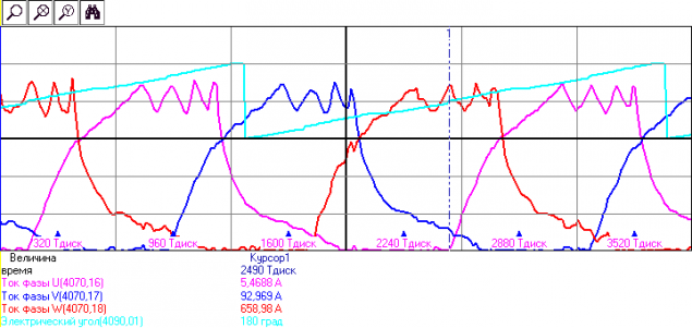
Feeding DC current in phases in accordance with the current position of the rotor can cause the motor to rotate. Phases can be a different number. Form a real drive current for the three phases of the show in the picture (current limit 600A):
However, the simplicity of the engine has to be paid. Since the engine is powered unipolar pulses of current / voltage, directly "on the net" it can not be enabled. Be sure you want to converter and rotor position sensor. Moreover, the inverter is not classical (type shestiklyuchevoy inverter) for each phase of the converter for SRD must be half a mile, as in the photo at the beginning of this section. The problem is that in order to reduce the cost of components and improving the layout of transducers power switches and diodes are often manufactured separately: commonly used finished modules which contain simultaneously two switches and two diodes - the so-called rack. And that they most often have to put in the converter for VID SW, half power switches simply leaving untapped: an excessive inverter. Although in recent years some manufacturers have released products IGBT modules designed specifically for SRD.
Next problem - a torque ripple. By virtue of the toothed structure and pulse current moment rarely get stable - most often it is pulsating. This somewhat limits the applicability of engines for motor vehicles - who want to have a pulsating torque on the wheels? In addition, by such pulses pulling force is not very good feel of the engine bearings. The problem is solved several special profiling phase current form, as well as increasing the number of phases.