Dissect a cheap robot vacuum cleaner
 Bashny.Net
Good time sutok.
Today study giblets and the scheme of the budget of the robot cleaner Electros Agait EC MINI .
Given the primitive algorithm, the robot can be called very conditional.
A lot of text, images and interviews for a snack.
When buying any Beyond Expectation was not, although I was pleasantly surprised - it works, and even collect dust)).
Since this model is the youngest, will not discuss the functionality of the product "out of the box" and look at the scope for rukoprkiladnichestva and upgrades.
I this device is seen as a ready platform for DIY robot cleaner.
The first candidate for an upgrade of course begs the brain.
The power unit to start can be left available, and as a controller to use something from the clan Arduino.
With the implantation of the current scheme should be no problem, because Original version uses a microcontroller EM78P153K powered 5V 14 pin package (minus 2 O power) Total 12 pins to communicate with the scheme.
A general view of the innards h4>
What do we offer manufacturer of this miracle? H4> Charger 19V 600 mA
Consider the diagram h4> Driving copied from the board, so there may be inaccuracies.
Walk on the main nodes h5> Q1, Q2, Q15 This key charging the battery. Note that here it is charging just in time to limit the maximum current through the 5 watt resistor R73. No control is not provided, so that looking at the diagram I clone your batteries are charged IMAX retirement charge on ΔV, live longer.
Drivers wheel motors h4>
Sensors protection from falling down the stairs h4>
«Summary" on the legs of the microcontroller h4> In the case of an active 0 will mark.
Result h4> In my opinion the most important drawback of the current scheme is combined trip signals bumper sensors and fall, so at the current algorithm cleaner obstacles encountered when moving "right" is simply rotated 180 ° and goes away from him to the other side of and so several times along the same path. Therefore, it is desirable to divide the signals for a more adequate response to the obstacles and the "end of the earth».
course needed! What is needed, but in the current development of this technology yet. No, it is not necessary I myself (a) is pleased to tidy as can be trusted with this heartless piece of iron! What is needed, but the cost of holding back. Voted 417 people. 43 people abstained. Only registered users can vote in polls. Sign , please.
Source: geektimes.ru/post/243957/

Today study giblets and the scheme of the budget of the robot cleaner Electros Agait EC MINI .
Given the primitive algorithm, the robot can be called very conditional.
A lot of text, images and interviews for a snack.
When buying any Beyond Expectation was not, although I was pleasantly surprised - it works, and even collect dust)).
Since this model is the youngest, will not discuss the functionality of the product "out of the box" and look at the scope for rukoprkiladnichestva and upgrades.
I this device is seen as a ready platform for DIY robot cleaner.
The first candidate for an upgrade of course begs the brain.
The power unit to start can be left available, and as a controller to use something from the clan Arduino.
With the implantation of the current scheme should be no problem, because Original version uses a microcontroller EM78P153K powered 5V 14 pin package (minus 2 O power) Total 12 pins to communicate with the scheme.
A general view of the innards h4> 
To plan the implantation of the new, we first need to submit any actuators and "senses" that have "animal».

What do we offer manufacturer of this miracle? H4> Charger 19V 600 mA 
Battery Ni-MH AA of 12 elements with the promised capacity of 800 mA-h 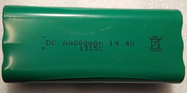


2 wheel module with commutator motors. B> 
Internal device

Planetary gear

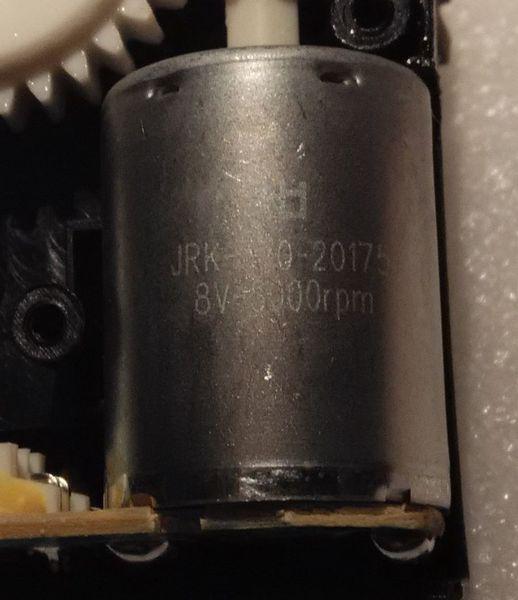
Engine
The centrifugal fan draws air through the bag. B> 12V 0.5A

2 drive side brushes. B> 
3 IR sensor protection from falling down the stairs. B> Outside

Inside

Bumper collision sensor 1 (regular slotted opto-coupler). B> 
Slit optocoupler presence of the top cover. B> 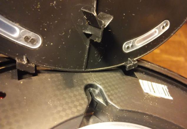
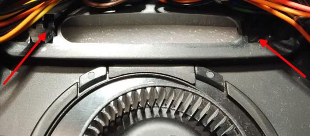
In this model, the optical sensor is no vacuum in the suction opening (IR LED photodiode +) and the corresponding part of the circuit. Although the space in the housing and wiring on the board there, so if you want you can add.


Consider the diagram h4> Driving copied from the board, so there may be inaccuracies.

Unnamed transistors is something small SOT23. Q1, Q9, Q10 with Chinese markings Y1 ostalnye- CR, identify what kind of transistors failed. To understand the logic of the circuit is not particularly necessary. Unnamed diodes 1N4148 likely in SMD version, and their type is not particularly important.
Strapping mkrokontrollera not. Generally not. So it is not on the circuit, there is a reference to the conclusions. He corny powered by + 5V and the other legs apart under the scheme.

Walk on the main nodes h5> Q1, Q2, Q15 This key charging the battery. Note that here it is charging just in time to limit the maximum current through the 5 watt resistor R73. No control is not provided, so that looking at the diagram I clone your batteries are charged IMAX retirement charge on ΔV, live longer.
Stabilizer 8.25V to MS34063 portrayed unit, as the chip is enabled on the template. Resistor Rsc (see datasheet) 0.22 Ohm. Ie present current limit, not only to protect the chip itself, for something a little less.
From him feed wheel module and the drive side brushes.
On dual comparator LM393 assembled control subsidence power wheel modules and side brush (in the case of jamming by foreign objects or fur. Fault) and discharge the battery. These two conditions for the controller one event.
The suction fan is switched on with the drive side brushes transistor Q24. The fan is powered almost directly (minus the voltage drop across the diode D16 and open transistor) from the battery. Acceleration, though:-) opposite side brushes feed 8.25V low voltage minus a drop of 3 diodes and transistor open.
Optocouplers JK1 and JK2 - slotted transistor. JK2 normally darkened (lid closed -tranzistor closed) and JK1 normally Highlights (bumper will not put his -tranzistor open)
Transistor Q25 assembled key switching LED power optocouplers and the entire assembly of sensors fall. In the presence of 19V charger is closed, in all other cases open.
Transistor Q8 assembled circuit monitoring the presence of 19V charger. The signal goes to the 7 pin. microcontroller. There also is connected phototransistor optocouplers cover. Ie connected power supply and open the cover for the controller one event. How did the controller distinguishes when the cover is open, and when the charger is connected? According to the bumper. When the charger is shaded from the phototransistor to power-off LED (key Q25). So if you open the lid and press the bumper when disconnecting the charger cleaner will think that it is charging, and it must be on the surface to have failed the drop sensor (with the charger are disabled Q25). This is payback for extreme simplification scheme. Charging mode indicated by a flashing green LED (in the lower left corner of the diagram). In order not to mislead (or may not scare) by a vacuum cleaner that shows charging without charger designers just do not give thanks to the flashing LED transistor Q9, although the first output of the microcontroller on the LED goes meander. Costa kostyliki.
Drivers wheel motors h4> 
Nothing remarkable not stand out.
Works just - on both inputs logic 0 - stand
Give one to one input - or go forward or backward.
Give two 1-tzu sadim + VCC Motor on the ground. Protection "from the fool" is not, so that two or 0 or a 1-tse.

Sensors protection from falling down the stairs h4> 
Circuitry predstavlyalyut a pair of LED optical -fotodiod directed onto the surface, wherein the photodiode is structurally more remote from the surface and may be partially covered with an adjustable shutter for switching the selection height (photo paper is in the beginning). For otvyazki of light levels in the room led some frequency modulated.
Approximate scheme for understanding the operating principle. The highlighted part individually for each channel, the first generator and a comparator at the last opreratsionnike common to all.
Exert their activity logic 1 to the diode D2
Operation of sensors fall and stop bumper obstacle to the microcontroller is a single event.

«Summary" on the legs of the microcontroller h4> In the case of an active 0 will mark.
1 Green LED
2.Bamper ran into an obstacle or load any drop sensor - active 0
3.Bazzer (beeper)
4. + 5V
5. Drawdown power motor brushes and wheels and low battery.
6.Vklyuchenie suction fan and side brushes.
7.Podklyucheno battery cover is open or - active 0
8. The left wheel
9. The left wheel
10. Connect the charger key - active 0
11. GND
12. Right wheel
13. Right wheel
14. Red LED.
Result h4> In my opinion the most important drawback of the current scheme is combined trip signals bumper sensors and fall, so at the current algorithm cleaner obstacles encountered when moving "right" is simply rotated 180 ° and goes away from him to the other side of and so several times along the same path. Therefore, it is desirable to divide the signals for a more adequate response to the obstacles and the "end of the earth».
Also it would be nice to add intelligence scheme charge.
Now you can unsolder native microcontroller connected * uino, or whatever you like and invent their own algorithms, but it will be in the second part. Do I need a robot vacuum cleaner in the house?
course needed! What is needed, but in the current development of this technology yet. No, it is not necessary I myself (a) is pleased to tidy as can be trusted with this heartless piece of iron! What is needed, but the cost of holding back. Voted 417 people. 43 people abstained. Only registered users can vote in polls. Sign , please. Source: geektimes.ru/post/243957/
Tags
See also
New LittleBits - banana now (actually with Wi-Fi)
10 reasons why Nikola Tesla can be called the greatest scientists in the history of insane
WHY CAN Nikola Tesla called the greatest mad scientist in history?
Gödel's incompleteness theorem in 20 minutes
Iceland is going to use the new high-temperature wells for energy
Breed cats. Part 2
Non-rocket spacelaunch
GOkey: data cable, battery, USB flash drive and detector keys in one package
These six people have died in solitude. But they did not find the body for years!
60 facts about Austria through the eyes of Russians