1192
Putting laser projector available parts
UPD: files are added to the board DAC GitHub
I originally planned to make Лазерную harp , but yet to get the intermediate result - a device that can be used as a laser projector - laser to draw various figures recorded in the file format ILDA. I am aware that many who take up the assembly of the laser projector, as a device to control galvanometer (and did not understand how best to translate into Russian blend "galvo scanner & quot;), using a slightly modified cheap sound cards for the PC. I went a different way, because ultimately I need to be fully self-contained unit which can work without a computer.
Let's see what is in my laser projector. The cost of all parts was about 8,000 rubles, of which more than half - a 70mW laser module.
Гальванометры and drivers for them to deflect the laser beam along the axes X / Y 70mW 532nm laser module powered by 5V Dragon Lasers SGLM70 Texas Instruments Stellaris Launchpad A homemade card with DAC AD7249BRZ Power Supply < /
Hardware h4> On my system using Stellaris Launchpad as the "brain" (because it is fast and has hardware support for USB) and 12-bit two-channel DAC with Serial Interface Analog Devices AD7249BRZ . To control the deflection of the beam at the input driver must apply an analog signal in the range of -5 to 5 volts. DAC AD7249BRZ just able to work in this mode (and also from 0 to 5 volts, and 0 to 10 volts). For him, I threw up in the Eagle a special fee, which is connected to the Stellaris Launchpad. The board requires a bipolar power supply, which is obtained by means of chip ICL7660 . To convert a single output voltage supplied to the galvanometer power supply (15V) as necessary to me, I used a linear regulator LM317, which later turned out to be the best solution, especially for the power of the laser module - because LM-ka with a large heatsink (seen in the video) after 10 minutes the work is heated to 70 degrees without heat sink, it just very quickly overheated and disconnected from overheating (and with it the laser module, which is why I initially decided that it burned and nearly postponed a couple of bricks, because when re-energized it does not include - as already it turned out so long until cool chip).
The modified laser module with a file h6> Schematic and board AD7249BRZ presented below. Perhaps the attentive reader will find in the scheme of error, because it for reasons unknown to me does not seem to work with a part of an operational amplifier, which is designed to make the output of the circuit балансным for greater protection from interference. My copy instead of the balanced signal outputs unbalanced, but nevertheless, everything works fine.
Soft h4> This seems the most interesting things about the end of the iron, so go to the soft-parts. It consists of two parts - a utility for the PC and the firmware for the Stellaris Launchpad, which implements the USB bulk-unit with its own packet format of 32 bits each. The format of the sample is described by the following structure:
I originally planned to make Лазерную harp , but yet to get the intermediate result - a device that can be used as a laser projector - laser to draw various figures recorded in the file format ILDA. I am aware that many who take up the assembly of the laser projector, as a device to control galvanometer (and did not understand how best to translate into Russian blend "galvo scanner & quot;), using a slightly modified cheap sound cards for the PC. I went a different way, because ultimately I need to be fully self-contained unit which can work without a computer.
Let's see what is in my laser projector. The cost of all parts was about 8,000 rubles, of which more than half - a 70mW laser module.
Гальванометры and drivers for them to deflect the laser beam along the axes X / Y 70mW 532nm laser module powered by 5V Dragon Lasers SGLM70 Texas Instruments Stellaris Launchpad A homemade card with DAC AD7249BRZ Power Supply < /
Hardware h4> On my system using Stellaris Launchpad as the "brain" (because it is fast and has hardware support for USB) and 12-bit two-channel DAC with Serial Interface Analog Devices AD7249BRZ . To control the deflection of the beam at the input driver must apply an analog signal in the range of -5 to 5 volts. DAC AD7249BRZ just able to work in this mode (and also from 0 to 5 volts, and 0 to 10 volts). For him, I threw up in the Eagle a special fee, which is connected to the Stellaris Launchpad. The board requires a bipolar power supply, which is obtained by means of chip ICL7660 . To convert a single output voltage supplied to the galvanometer power supply (15V) as necessary to me, I used a linear regulator LM317, which later turned out to be the best solution, especially for the power of the laser module - because LM-ka with a large heatsink (seen in the video) after 10 minutes the work is heated to 70 degrees without heat sink, it just very quickly overheated and disconnected from overheating (and with it the laser module, which is why I initially decided that it burned and nearly postponed a couple of bricks, because when re-energized it does not include - as already it turned out so long until cool chip).
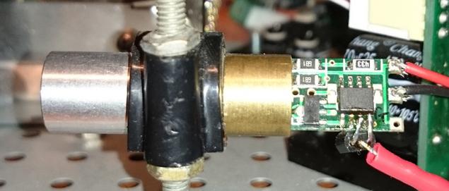
The laser module is not natively supported TTL-modulation, so when I got tired of just driving laser in different directions, I thought about that when the time is switched on and off the beam. This involved modifying the laser module soldering iron. Fortunately, almost all Chinese laser modules are very similar to each other, simple, and are made on the operational amplifier LM358. Solder at his feet 3 and 4 (non-inverting input and the ground, respectively) emitter and collector first got bipolar transistor 2N4401, I thus had the opportunity to modulate the laser operation, feeding a control signal to the base of transistor:

The modified laser module with a file h6> Schematic and board AD7249BRZ presented below. Perhaps the attentive reader will find in the scheme of error, because it for reasons unknown to me does not seem to work with a part of an operational amplifier, which is designed to make the output of the circuit балансным for greater protection from interference. My copy instead of the balanced signal outputs unbalanced, but nevertheless, everything works fine.

I hope you're not afraid of the terrible images from the card with a touch chip pins, which was formed after wiping with ethyl alcohol. Incidentally, the reason why flux laundered recommends isopropyl alcohol, because it does not leave such residue. Incidentally, it is interesting that such kind of connectors with a latch on the board - it plugs Molex (22-23-2021 socket, plug 22-01-3027, 08-50-0114 Contact Fork), ordering them through Digikey, since the Chinese, they are somehow obscenely expensive.

Soft h4> This seems the most interesting things about the end of the iron, so go to the soft-parts. It consists of two parts - a utility for the PC and the firmware for the Stellaris Launchpad, which implements the USB bulk-unit with its own packet format of 32 bits each. The format of the sample is described by the following structure:
& lt; code class = & quot; cpp & quot; & gt; typedef struct {unsigned x: 12; // Coordinate X unsigned rx: 4; // Flag (on / off laser) unsigned y: 12; // Coordinate Y unsigned ry: 4; // Not used} sample_t; & lt; / code & gt; pre> The device uses a USB-buffers of 512 bytes, in which PC with some margin, and at such a rate as not to cause overflow or underflow of the buffer writes data. Used galvanometers designed to map 20,000 points per second, that is required is the sampling frequency. The functions of the data from the USB processing speed is regulated by the banal SysCtlDelay code> pre>. By adjusting the value of the system can be adjusted so that the ILDA test image displayed correctly:
The green LED on the video at the beginning of Lent flashes after processing each packet of 20,000 samples. That is, ideally, it should blink exactly 1 times per second.
The software part of the PC is based on the playilda.c code> pre> from the package OpenLase < / a>, but cut out all unnecessary and instead communicate with the server JACK uses libusb to send data packets to the Stellaris Launchpad.
The source code of the program for the PC & lt; code class = & quot; cpp & quot; & gt; #include & lt; stdlib.h & gt; #include & lt; sys / time.h & gt; #include & lt; time.h & gt; #include & lt; stdio.h & gt; #include & lt; string.h & gt; #include & lt; libusb-1.0 / libusb.h & gt; #include & lt; iostream & gt; #include & lt; string & gt; #include & lt; vector & gt; #define MAGIC 0x41444C49 static inline uint16_t swapshort (uint16_t v) {return (v & gt; & gt; 8) | (v & lt; & lt; 8); } Float scale = 1.0; typedef struct {uint32_t magic; uint8_t pad1 [3]; uint8_t format; char name [8]; char company [8]; uint16_t count; uint16_t frameno; uint16_t framecount; uint8_t scanner; uint8_t pad2; } __attribute __ ((Packed)) ilda_hdr; #define BLANK 0x40 #define LAST 0x80 typedef struct {int16_t x; int16_t y; int16_t z; uint8_t state; uint8_t color; } __attribute __ ((Packed)) icoord3d; typedef struct coord3d {int16_t x; int16_t y; int16_t z; uint8_t state; coord3d (int16_t x, int16_t y, int16_t z, uint8_t state): x (x), y (y), z (z), state (state) {}} coord3d; typedef struct {std :: vector & lt; coord3d & gt; points; int position; } Frame; frame rframe; int subpos; int divider = 1; int loadildahdr (FILE * ild, ilda_hdr & amp; hdr) {if (fread (& amp; hdr, sizeof (hdr), 1, ild)! = 1) {std :: cerr & lt; & lt; & quot; Error while reading header & quot; & lt; & lt; std :: endl; return -1; } If (hdr.magic! = MAGIC) {std :: cerr & lt; & lt; & quot; Invalid magic & quot; & lt; & lt; std :: endl; return -1; } If (hdr.format! = 0) {fprintf (stderr, & quot; Unsupported section type% d \ n & quot ;, hdr.format); return -1; } Hdr.count = swapshort (hdr.count); hdr.frameno = swapshort (hdr.frameno); hdr.framecount = swapshort (hdr.framecount); } Int loadild (const std :: string & amp; file, frame & amp; frame) {int i; FILE * ild = fopen (file.c_str (), & quot; rb & quot;); if (! ild) {std :: cerr & lt; & lt; & quot; Can not open & quot; & lt; & lt; file & lt; & lt; std :: endl; return -1; } Ilda_hdr hdr; loadildahdr (ild, hdr); for (int f = 0; f & lt; hdr.framecount; f ++) {std :: cout & lt; & lt; & quot; Frame & quot; & lt; & lt; hdr.frameno & lt; & lt; & quot; of & quot; & lt; & lt; hdr.framecount & lt; & lt; & quot; & quot; & lt; & lt; hdr.count & lt; & lt; & quot; points & quot; & lt; & lt; std :: endl; icoord3d * tmp = (icoord3d *) calloc (hdr.count, sizeof (icoord3d)); if (fread (tmp, sizeof (icoord3d), hdr.count, ild)! = hdr.count) {std :: cerr & lt; & lt; & quot; Error while reading frame & quot; & lt; & lt; std :: endl; return -1; } For (i = 0; i & lt; hdr.count; i ++) {coord3d point (swapshort (tmp [i] .x), swapshort (tmp [i] .y), swapshort (tmp [i] .z), tmp [i] .state); frame.points.push_back (point); } Free (tmp); loadildahdr (ild, hdr); } Fclose (ild); return 0; } Short outBuffer [128]; int process () {frame * frame = & amp; rframe; short * sx = & amp; outBuffer [0]; short * sy = & amp; outBuffer [1]; for (int frm = 0; frm & lt; 64; frm ++) {struct coord3d * c = & amp; frame- & gt; points [frame- & gt; position]; * sx = 4095 - (2047 + (2048 * c- & gt; x / 32768)) * scale; * sy = (2047 + (2048 * c- & gt; y / 32768)) * scale; if (c- & gt; state & amp; BLANK) {* sx | = 1 & lt; & lt; 15; } Else {* sx & amp; = ~ (1 & lt; & lt; 15); } + Sx = 2; sy + = 2; subpos ++; if (subpos == divider) {subpos = 0; if (c- & gt; state & amp; LAST) frame- & gt; position = 0; else frame- & gt; position = (frame- & gt; position + 1)% frame- & gt; points.size (); }} Return 0; } Int main (int argc, char ** argv) {libusb_device_handle * dev; libusb_context * ctx = NULL; int ret, actual; ret = libusb_init (& amp; ctx); if (ret & lt; 0) {fprintf (stderr, & quot; Could not initialize libusb \ n & quot;); return EXIT_FAILURE; } Libusb_set_debug (ctx, 3); dev = libusb_open_device_with_vid_pid (ctx, 0x1cbe, 0x0003); if (dev == NULL) {fprintf (stderr, & quot; Can not open device \ n & quot;); return EXIT_FAILURE; } Else printf (& quot; Device opened \ n & quot;); if (libusb_kernel_driver_active (dev, 0) == 1) {fprintf (stderr, & quot; Kernel driver active \ n & quot;); libusb_detach_kernel_driver (dev, 0); } Ret = libusb_claim_interface (dev, 0); if (ret & lt; 0) {fprintf (stderr, & quot; Could not claim interface \ n & quot;); return EXIT_FAILURE; } // To maintain our sample rate struct timespec ts; ts.tv_sec = 0; ts.tv_nsec = 2000000; memset (& amp; rframe, 0, sizeof (frame)); if (loadild (argv [1], rframe) & lt; 0) {fprintf (stderr, & quot; Failed to load ILDA \ n & quot;); return EXIT_FAILURE; } While (1) {process (); if (nanosleep (& amp; ts, NULL)! = 0) fprintf (stderr, & quot; Nanosleep failed & quot;); ret = libusb_bulk_transfer (dev, (1 | LIBUSB_ENDPOINT_OUT), (unsigned char *) & amp; outBuffer, 256, & amp; actual, 0); if (ret! = 0 || actual! = 256) fprintf (stderr, & quot; Write error \ n & quot;); } Libusb_release_interface (dev, 0); libusb_close (dev); libusb_exit (ctx); return 0; } & Lt; / code & gt; pre>
The functions of the main () code> pre> using nanosleep also governed by the frequency with which new data is sent to the microcontroller.
Full source code of the controller firmware are available .
 Plans for the Future  h4> It is planned to finish these things still to a state similar to the originally intended laser harp. For this purpose only one instead of two mirrors, since the laser beam moves along only one axis. The principle of operation of the harp is that the controller ignites and extinguishes laser beam at certain times it creating laser "keyboard" in the air. Artist, blocking hand in glove reflective bright laser beam activates the photosensitive element at the base of "harp". Since the microcontroller knows at what moment which part of the keyboard, he "painted" that can determine which of the beams has been blocked. Then it's up to the formation of the corresponding MIDI-message and sending it to a computer or connected to form a hardware synthesizer sound.


Source:
Plans for the Future h4> It is planned to finish these things still to a state similar to the originally intended laser harp. For this purpose only one instead of two mirrors, since the laser beam moves along only one axis. The principle of operation of the harp is that the controller ignites and extinguishes laser beam at certain times it creating laser "keyboard" in the air. Artist, blocking hand in glove reflective bright laser beam activates the photosensitive element at the base of "harp". Since the microcontroller knows at what moment which part of the keyboard, he "painted" that can determine which of the beams has been blocked. Then it's up to the formation of the corresponding MIDI-message and sending it to a computer or connected to form a hardware synthesizer sound.
Source: 


Phyode W / Me: sporty bracelet with "health indicator"
Samsung introduces a new series of SSD-drives 845DC EVO