Decorative lamps household RRT-W "Evlampiya"
 Bashny.Net
Frankly, I do not remember how it all began. Suppose, again I was bored and wanted some light at the end of the tunnel though, at least in the beginning. Little by little the desire shape in nightlight that turns on a wave of his hand. And subsequently transformed into a decorative lamp with adjustable brightness, different shades glow and all sorts of extra features. Namely, temperature display behind and lighting control room.
And all this happened because the cheapest interior lamps from IKEA, a couple of meters LED strip, Arduino, and a small handful of modules and components.
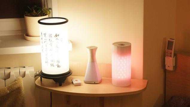
Meet Evlampiya h4> I would like some sort of bureaucratic language like "Lamp RRT-Z" Evlampiya "is intended to be used for decorative purposes within the premises", but then it will be necessary to write about strict adherence to instructions, what are absent. So I will be easier, especially since it is the basic principle of management Evlampiev.
.
So what she is able to:
1) Work nightlight
2) Work lamp background light
3) shows the temperature on the street
4) Work decorative lamp shade with manual change
5) Work decorative lamp shade with a cyclic change
6) to control the light in the room *
* Controls and switches Livolo radios-rosette chips SC / PT2260 / 2262 and similar fixed code.
As you might guess, the lamp is controlled horizontal and vertical movements. In this case, the horizontal sweep of controls or lamp, or switch modes in a circle (lamps, thermometers, hand rainbow, rainbow automatic).
The reason is that I wanted to somehow get away from all consoles, switches and other vayfay. To know, light and shades depend on, so to speak, sleight of hand. Hand, of course, mentioned conditional - fit any obstacle. But since people usually hands rather than obstacles in the future - the hand.
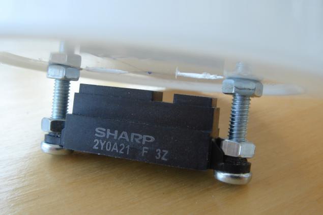
In view of this specificity chosen sensor - IR rangefinder Sharp, about which one person wrote that the target device - automatic urinal and others interested in that kind of a urinal, if some sensors family maximum working distance of about 40 cm. the other hand, I know that these sensors are used in a robotic vacuum cleaner to prevent collisions with obstacles.
Not the essence.
The working distance of the selected sensor - 80 cm (though in fact, seems to be much more), wherein the output voltage is higher the closer the object. But there is an obstacle approaching the threshold at which the voltage goes down, despite the fact that the obstacle becomes closer. Unpleasant but not fatal, especially in my case it's about 4 inches, which can compensate for the "recessed" into the design of the sensor.
After selecting the sensor, I suddenly realized that just light enough for me. And wanted a rainbow, and many other buns - once still in the tube will be the controller, whose resources are not used. So the list of components appeared LED RGB-tape instead of a simple transmitter and receiver 433 MHz, as well as transistor assembly for controlling tape. Last seemed more attractive than just a few field-effect transistors, do not ask why.
To leave no ambiguities. The receiver needs to obtain data on temperature and external commands - in fact it would be foolish to miss the opportunity to turn on and off the lamp with remote background lighting. The transmitter is required to control an external light: the background on the basis of conventional radio-controlled sockets and the top through radio switches Livolo.

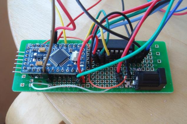
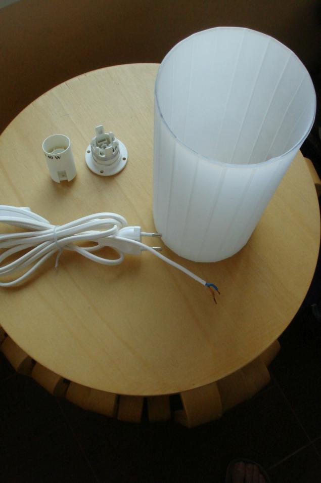
Accessories h4> In short, I had a lamp from IKEA, debug handkerchief Arduino Pro Mini, prototyping board, distance sensor Sharp, receiver and transmitter with amplitude modulation at 433 MHz RGB-LED tape of the Bank under beer, bottles of drinking water, a box of tooth powder, AC adapter 9V, fasteners and a handful of little wires. Not that it was enough to revive the orbital station "Mir", but Evlampiev quite enough.
So (links only as an example):
- Lamp Qarn ;
- IR distance sensors Sharp GP2Y0A21YK , and that's just datasheet ;
- Приемник 433 MHz - superheterodyne because regenerative receivers, I was disappointed. Either because they are, or because I can not do normal antenna;
- Передатчик 433 MHz subjective - pretty decent and, moreover, since the antenna;
- Arduino Pro Mini ;
- Transistor assembly ULN2003A ;
- LED strip RGB - to taste, I bought offline;
- Network adapter - also to taste, I lay some old 9V (at 12V, it might be better - in fact on the tape 12B);
- Aluminum cans of 0.5 liters out of any beverage;
- Plastic bottle with a diameter of the inner diameter aluminum cans;
- Bank dentifrice diameter to the inner diameter of the lamp. Similar to a (I bought at convenience stores);
- Prototyping board, building wires - to taste;
- Optional: capacitors 10 uF 0.1 uF 10k resistor.
Driving h4>
Capacitors and pull-up resistor optional, and are not given in the diagram. I used them as part of campaign against false positives, but in the end it turned out that the phantom potentials at anything.
. I hope that more or less correctly drawn.
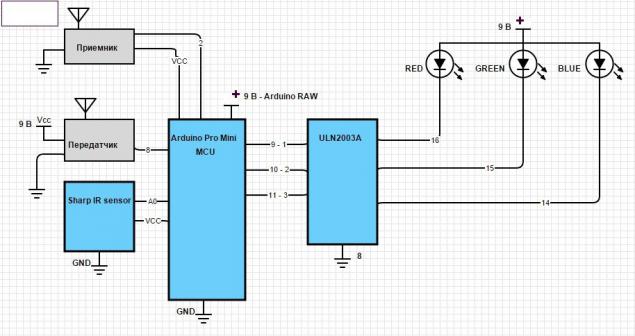
. well looks like what happened under the scheme. Excuse me, that's ugly. I am sure that you will definitely be better!
Be sure to pay attention to nutrition infrared sensor and receiver. They need no more than 5V, so they eat from the stabilizer Arduino, and not directly from the power supply.


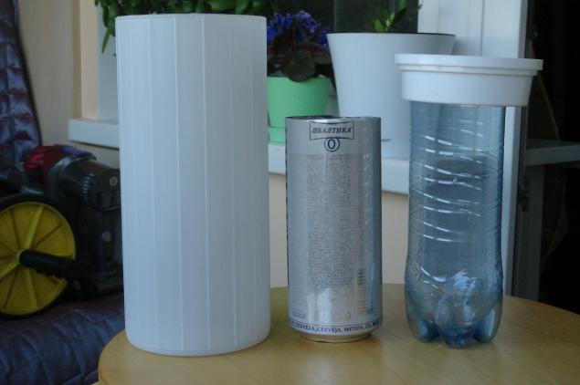
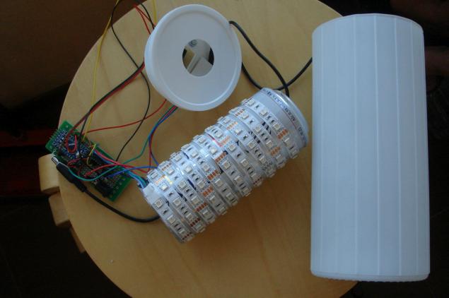
Miracle of miracles h4> Assembling all of this into a single unit was busy absolutely incredible. To begin with, except the lamp from IKEA also need a plastic bottle with a capacity of 0.5 liters, aluminum can of the same capacity out of any beverage and plastic can of tooth powder. That's because in my head there was a following concept: RGB-tape is glued to the aluminum can. It turns out some analogue of the famous Chinese "kukuruzin", which is placed inside the ceiling lamp.
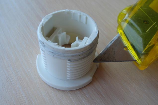
. original lamp, carefully divided into parts
Bank are needed to serve some heat sink and no means to observe the geometry drawn up so the light emitter. In the same bank on a plan of the creator (ie me) and fit the control board. But as the bank metal, then the short circuit protective primitive: laying the pre-trimmed inside a plastic bottle, which serves as an insulator.
Hence the law Eulampia: outer diameter of the bottle must not exceed the inner diameter of the can.
As for the banks from the tooth powder, it is demanded that, firstly, more or less aesthetically pleasing cover against dust and prying eyes top of the lamp. And at the same time - it is convenient to fix the sensor and place the receiver to the transmitter. After all, in a metal can have little chance of productive activities.
Other miracles in order:
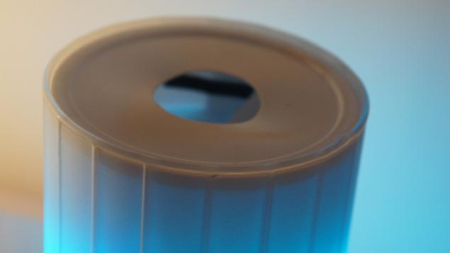
random bought a couple of meters LED strip just enough to wrap the jar Bank to carefully cut off the tip of the perfect rose into the lamp bottle insulator perfectly fit in the bank < / Bank from the tooth powder diameter almost fit into the inner diameter of the ceiling. "Almost" in this case means that there are minor violations geometry covers that partly due to the fact that the housing banks still compressed, and partly the fact that the lid of the jar had to make a hole for the IR sensor. ul > 
. approximately the deformation
"Kukuruzina" is attached to the lower dome in the lower mounting point regular patron. Of course, by this attachment had to break off the "extra" elements, but the fact remains.
According to my version of the assembly process is as follows:
1) Cut off the tip of aluminum cans and cut into its bottom hole corresponding to the diameter of the hole in the nut securing the lamp socket. Nut glued to the bottom of the banks - in the future it will be all screwed onto the cartridge mount.
. like this
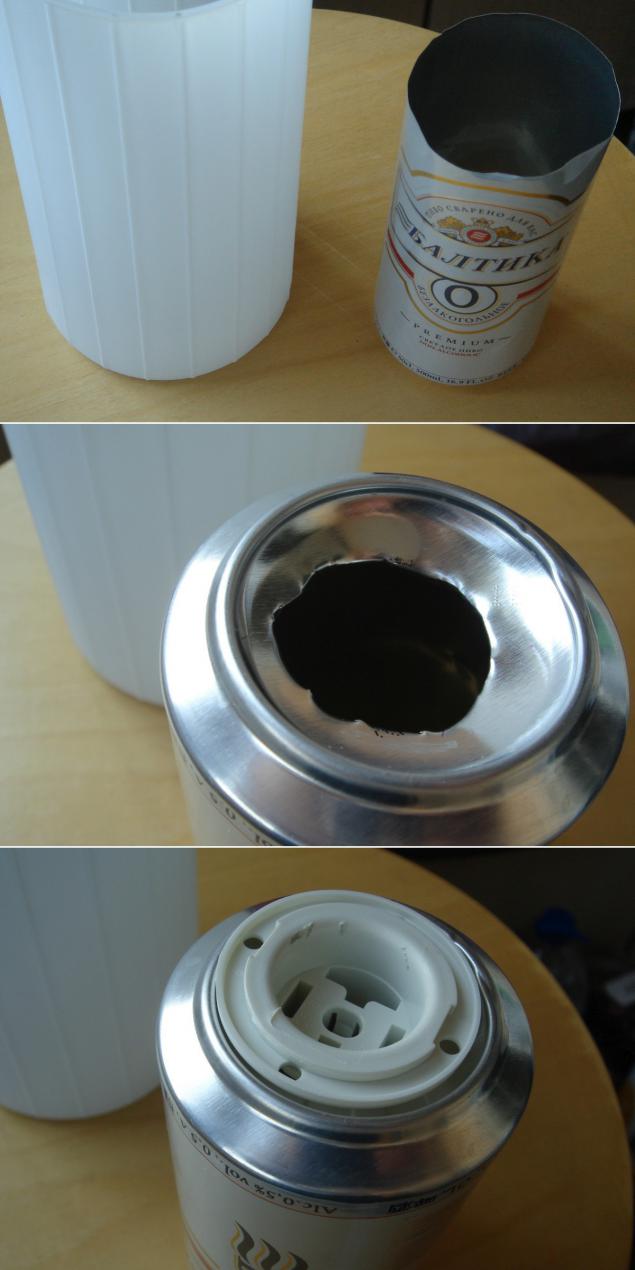
2) From the mounting cartridge removes its own cartridge and details that prevent threading the wire into the hole with a plug to power the controller.
.
3) Here I would have to carefully cut the bottom of the bottle and cut off her nose, so that on the one hand the nose, being placed close to the bottom of the banks, the controller eliminates contact with metal walls, and on the other, so that the bottle does not protrude beyond the banks height. But as the two made a mistake, the result put on the bottom of the banks bottom of the bottle (with the hole, of course, and the top (cut excessively nose down) - the rest of the bottle.
.
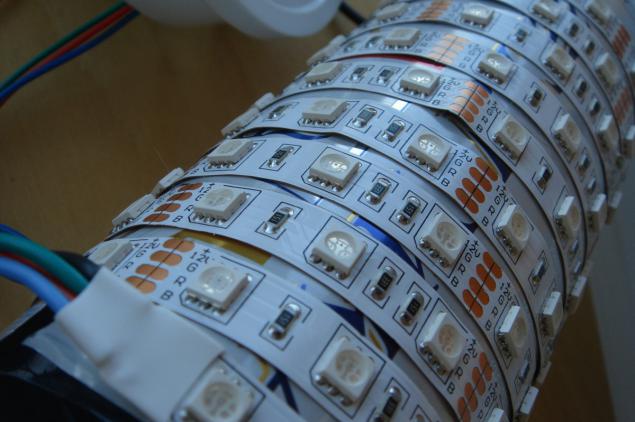
4) LED strip is glued around the banks so as to create a sufficient density of LEDs and simultaneously keep in length (2 meters). Pasted from the bottom of the banks, input leads up to then lower them into the jar, to the controller.
.
5) In a clean pot of tooth powder Do the two large holes. At the bottom and lid both at the transmitter. Openings shall be not less than the diameter of the sensor. In the bottom of the hole can be almost any shape, but optimally rectangular, because next to him to do a couple of smaller holes - for mounting studs sensor. The cover I was comfortable making a round, because it was actually marked out by stamping factory, and I carefully cut his normal office-a paint knife.
. First I drilled two round holes for the sensor, but when it became clear that it needs to move from the edge of the banks, then had to make a real "failure", or is reflected from the bottom of the banks
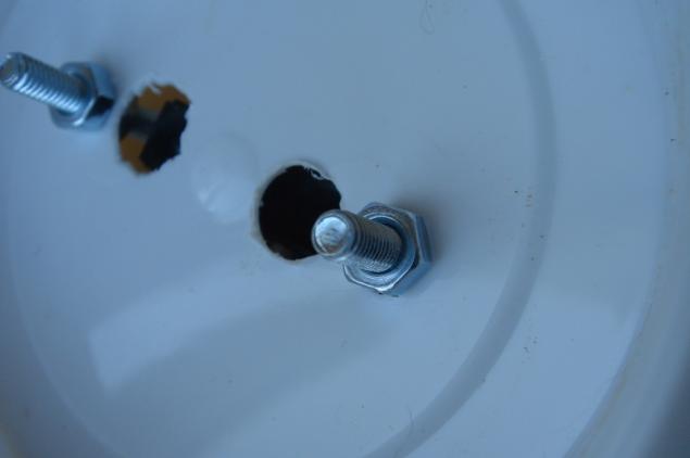
Carefully drill out the hole for the sensor M4 (if there is a hardware M3 - take it and do not drill) and skewer it on the screws, locking nuts.
.
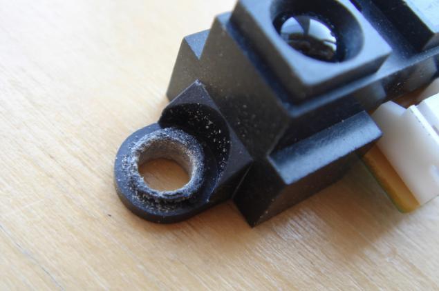
Screw on the screws still on the nut and threaded through holes in the bottom of their banks, and on top - even on the nut. This design allows you to adjust the position of the mechanical sensor to fine-tune the baseline. Looking ahead - basic level is the level at which Evlampiya believes that her hand was covered, and we should all turn off.
.
The bank will also require holes for receiver and transmitter 433 MHz, that there must also be more or less neatly tucked away.
6) connected to the controller LED strips, IR sensor, transmitter and receiver 433 MHz. Thread the bottom to cover the power cable and is also connected to the controller.
. are already partially seen a rectangular hole in the bottom of the "tooth" banks
7) Puts the controller kukuruzinu, close the entire structure can of tooth powder.
8)? !!!
9) PROFIT !!!
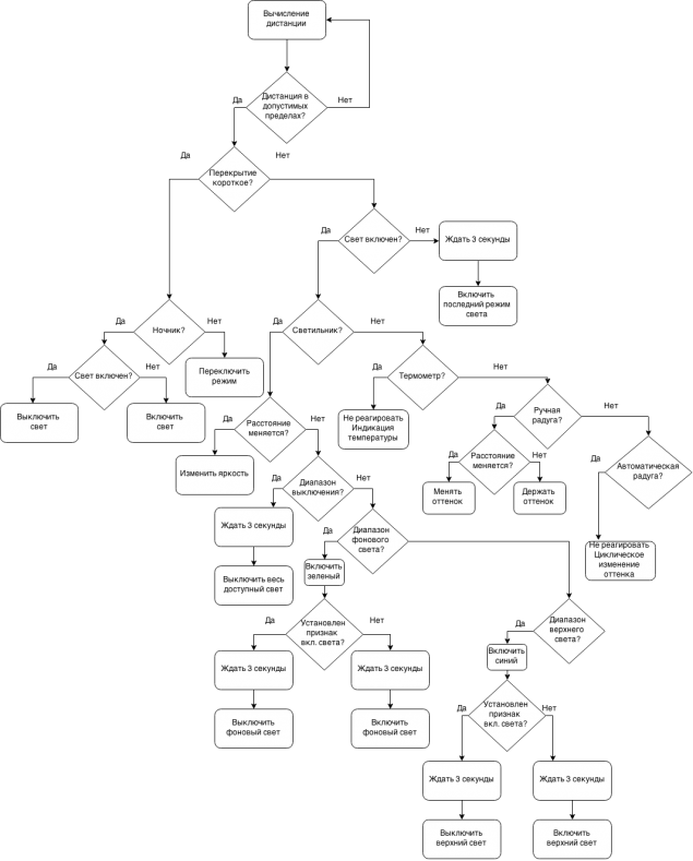
algorithm h4> Here I have tried to portray the algorithm kernel functions Eulampia, excluding radio control. Also, this algorithm - a part of the executable cycle indefinitely.

Code h4>
In addition to the code required two libraries:
RC Switch Livolo Also, you first need to find out empirically, and then in the section variables to set the range of the sensor, depending on how you place it.
This variable top and bottom , comments marked "top zone adjustment" and "bottom zone adjustment».
The code also remained debug lines - if necessary, can turn.
p.s. Evlampiya until it receives the temperature mode display it has consistently flashes three colors and switches to the next mode.
All that is acquired by overwork
& lt; code class = & quot; cpp & quot; & gt; // beta 3 - calibrated range of the distance to a pro rata adjustment of brightness and hue // beta 4 - added Tally switchable external light, lamp remote control // beta 4 - compression of the input temperature values for fixed color temperatures // beta 4 - adjust the color temperature: / * -35 - -25 -25 0 Blue - Turquoise 15 -15 -15 - Light cyan 0 50 0 - 15 Light Green 85 15 - 20 100 Green 20 - 25 Yellow-green 170 25 - 30 Yellow-Red Raspberry 30+ 235 254 // RED: if (colorV & lt; 100) {targetR = colorV * 0.05; } Else {targetR = 5+ (colorV-100) * 1.29; } // GREEN if (colorV & lt; 75) {// 0 - 180 targetG = 2.4 * colorV; } If (colorV & gt; 75 & amp; & amp; colorV & lt; 100) // {180 - 254 targetG = 180 + (colorV-75) 2.96 *; } If (colorV & gt; 100 & amp; & amp; colorV & lt; 150) {// 254 targetG = 254; } If (colorV & gt; 150 & amp; & amp; colorV & lt; 200) // {254 - 154 targetG = 254 - (colorV-150) * 2; } If (colorV & gt; 200) {// 154 - 0 targetG = 154 - (colorV-200) * 2.85; } // BLUE if (colorV & lt; 100) {targetB = 254 - colorV * 2.54; } Else {targetB = colorV * 0.05; } * / #include & Lt; RCSwitch.h & gt; // Control sockets SC2260 / 2262 http://code.google.com/p/rc-switch/ #include & lt; livolo.h & gt; // Control switches Livolo #define txPin 8 // pin transmitter Livolo livolo (8); // Object Livolo RCSwitch mySwitch = RCSwitch (); // Object RC-Switch int weatherData = 0; unsigned long dimmerDelay, timerStart, timerStop, timerSwitchStart, timerSwitchStop, timerRange; // Timers int prevRange, nowRange, tempRange, switchRange, vectorRange, initRange, rangeFinder, tempC; byte nightLightLevel, rainbow, delta, redB, greenB, blueB, targetL, targetR, targetG, targetB, lastValueRGB; byte lightMode = 0; // Mode lamp (0 - nightlight 1 - lamp, 2 - thermometer, 3 - rainbow manual, 4 - Rainbow automatic) byte lastMode = 1; // Mode for the first call always lamp byte valueRGB = 0; // Brightness or hue (normalized value nowRange) boolean rainbowUp, followMeLight; // Direction rainbow boolean timing = false; // Sign running timer (hand over the lamp) boolean switchLock = false; // Sign the ban on switching to the removal of the hand lamp with boolean tempLock = false; // Sign a ban on the display temperature to produce a new boolean backLight = false; // Sign running back light boolean mainLight = false; // Sign of working skylight boolean nightLight = false; // Sign nightlight mode boolean tempRcvd = false; // Sign of the resulting temperature 65 // #define nightLightLimit brightness nightlight #define rangePin A0 // #define redPin obstacle sensor 9 // #define greenPin red green 10 // 11 // #define bluePin blue #define bottom 630 // bottom zone adjustment // #define top 135 top zone adjustment 20 // #define delta allowable deviation in determining the distance #define shortDelay 350 // delay for switching modes #define longDelay 3000 100 // #define timeOutRange spacing distance calculation is needed since & quot ; slip & quot; hand distance varies, and thus changing the brightness or color #define rainbowStep 75 // change interval shade of the rainbow 35 // #define dimmerStep speed mute nightlight void setup () {// Serial.begin (9600); pinMode (rangePin, INPUT); pinMode (redPin, OUTPUT); pinMode (greenPin, OUTPUT); pinMode (bluePin, OUTPUT); mySwitch.enableTransmit (txPin); // Allowed to remain mySwitch.enableReceive (0); // Allowed reception (interrupt 0 - & gt; pin 2) rgbLight (0, 0, 0); // Lamp is turned off lastMode = 1; // First inclusion is always in the mode of light timerRange = millis (); // Start the timer to periodically reading distance nowRange = getRange (); // First calculation distance} void loop () {// periodically calculating DISTANCE if ((millis () - timerRange) & gt; timeOutRange) {// distance calculation times timeOutRange prevRange = nowRange; // Memory of the previous value of the distance nowRange = getRange (); // The current value of the distance timerRange = millis (); // Reset the timer interval calculation distance // Serial.print (& quot; Range: & quot;); // Serial.println (nowRange); } // Ran his hand - start the timer and switching (if appropriate), detained hand - service functions (if needed) if ((nowRange & lt; bottom + delta) & amp; & amp; (nowRange & gt; top)) {// if the distance is greater than the threshold and less than the upper boundary if (nowRange & gt; bottom - delta) {// off the light before & quot; bottom & quot; as an indicator for holding hands with complete exclusion of (2 * delta) valueRGB = 0; } Else {valueRGB = 254 - map (nowRange, top, bottom, 0, 254); // Cast the current value to a range of 0 - 254 and & quot; revolution & quot; } // Serial.print (& quot; valueRGB: & quot;); // Serial.println (valueRGB); // Color map to change the background and skylight if (lightMode == 1) {// if the lamp mode if (valueRGB & gt; 70 & amp; & amp; valueRGB & lt; 110) {// if the hand in the middle of the lower half of followMeLight = true ; // Kill bit dimming white light is allowed only shade indicator lastValueRGB = valueRGB; // Memory of the last brightness values rgbLight (0, 255, 0); // Green color as an indicator of the ability to switch & quot; near & quot; Light // Serial.println (& quot; Set Green to 255 & quot;); } Else {if (valueRGB & gt; 175 & amp; & amp; valueRGB & lt; 215) {// if the hand in the middle of the upper half followMeLight = true; lastValueRGB = valueRGB; // Memory of the last brightness values rgbLight (0, 0, 255); // Blue color as an indicator of the ability to switch & quot; far & quot; Light // Serial.println (& quot; Set Blue to 255 & quot;); } Else {if (valueRGB & gt; 235) {// if the hand is at the upper limit followMeLight = true; lastValueRGB = valueRGB; // Memory of the last brightness values rgbLight (valueRGB, 0, 0);
Tags
See also
"How can I, as an ordinary schoolboy, designed and built their model 3D printer"
The big idea for a small computer desk
Complete energy autonomy or how to survive with solar panels in the province (Part 1. Theoretical)
Designer of the dice. Make cheaper than buying
Martin Gardner, board games and 3D printing
Hikaru skirt with his hands
Printer Review Freaks3D Kit from Elec Freaks - all to be honest
Field tests astrotrekera
How to make a Dance pad for Dance Dance Revolution
As I developed a device for pumping cot