Another smart plug for the next smart home
 Bashny.Net
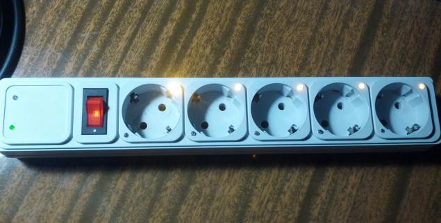
Many years dreamed of creating a smart home, but each time the problem has stopped communication modules (sockets, switches and sensors) to the city center and with each other. But progress does not stand still, more and more common information about microcontrollers with embedded transceivers pushed me again to go back to my old idea. In this post I will talk about how to create a "smart jack" (actually a line filter), which is represented in the image below.
Everything else under the cut. Caution Lots of pictures.
Introduction h4> First I must say that in the city where I live now, a very big problem with the electronic components (resistors at 5p. Thing, but the microcontroller then do not hear). All you have to order or ask me to convey his comrades of the more advanced in this respect places. I hope this information will explain the possible questions on the use of those components. This is not the first time my device and, through the use of ready-made modules, the need to draw diagrams eliminated. Represented only by a key diagram triac.
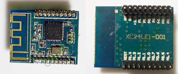
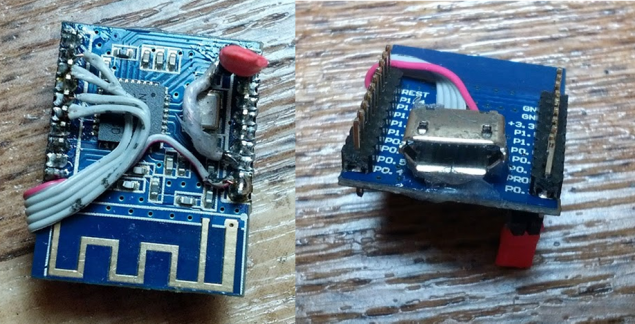
Components h4> ordered from our favorite friends from under heaven wonderful modules with soldered nRF24LE1. About this microcontroller already written a lot on the Habré ( here , and here , and yet here here ), and it really helped to start.
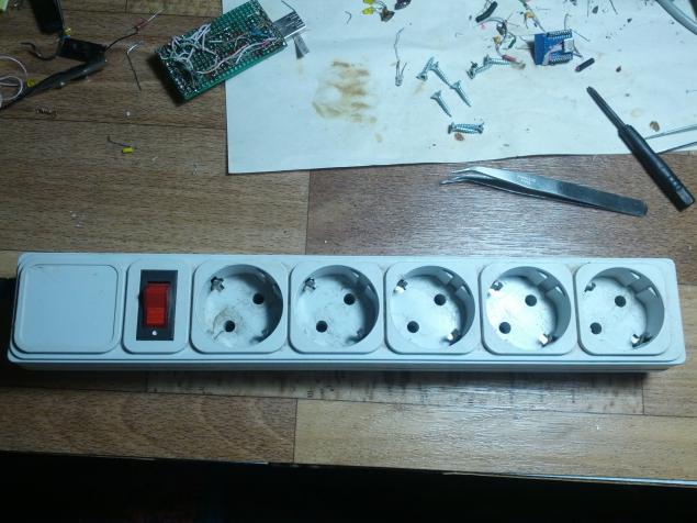
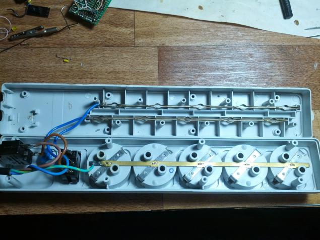
The development process h4> To start dismantled a network filter that would understand, if I have enough space.
functional h4> Unfortunately I can not put the firmware, because it is very confusing. Written with the work of the network with many devices, and in it a bunch of superfluous. If the community would be interested and I finally got an invite then publish everything in the next post. It is noteworthy that no clever algorithm is not there. It all boils down to a simple antsy pins on / off. No Shima and so on. Simple flashing LED (power modules for MC - normal LEDs)
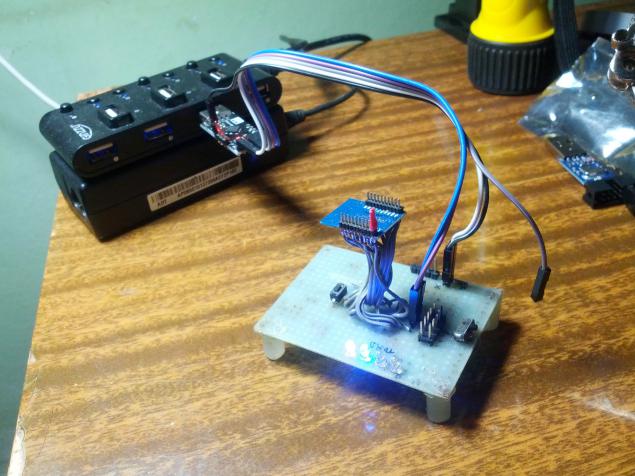
A little bit about the server h5> The server is the same module nRF24LE1, connected via USB-UART converter to the PC from which the Java application goes through the operation of other devices in the network. Photo below
Conclusion h4> Surge protector is already working for the benefit of my house. Soft yet moist and the meaning of his show and no blush.
The LEDs should be set perpendicularly, and for particularly wealthy plexiglass, I recommend to make a glowing stroke. Be cool! Self radio module should install in the opposite direction of the voltage input. Interference less, and more places. Use short microUSB It is worth adding persistence function pins during power failure. Himself plan in the new version of firmware do it
Special thanks to Associate Professor Yuri Ivanovich Ivanov (Department. Of ACS, SFU) for assistance in the development of other types of capacitor and power supply units. Although in this project do not, I will use them in the following, and be sure to tell you about it, if the community would approve this post.
Expect criticism but rather praise and suggestions to improve the design.
Documentation required h5> Даташит on nRF24LE1

Everything else under the cut. Caution Lots of pictures.
Introduction h4> First I must say that in the city where I live now, a very big problem with the electronic components (resistors at 5p. Thing, but the microcontroller then do not hear). All you have to order or ask me to convey his comrades of the more advanced in this respect places. I hope this information will explain the possible questions on the use of those components. This is not the first time my device and, through the use of ready-made modules, the need to draw diagrams eliminated. Represented only by a key diagram triac.
Components h4> ordered from our favorite friends from under heaven wonderful modules with soldered nRF24LE1. About this microcontroller already written a lot on the Habré ( here , and here , and yet here here ), and it really helped to start.
My modules, unlike most reviewed Habre, smaller in size and have a PLS with a small step (by the way, can tell the community how to call these pins and where to get a mate).
As a martyr modernized selected usual, already tested by accountants and cleaners, power filter. I rubbed it on as I could, but some fatigue from the constant kicking legs there.
Just from China were ordered triacs BTA16 (600v, 16A) and opto-triacs MOC3063. Rassypuha part was partly bought in addition.
So, in the battle!


The development process h4> To start dismantled a network filter that would understand, if I have enough space.
Designated wagon and cart grabs.
Next to the firmware nRF24LE1 decided to use the microUSB connector. Contacts missing, but you need to pull PROG input to the power supply to the device into programming mode. Decided to do a simple jumper (who himself had to do from shrinking and wire).
A single, large, thank you post from MaksMS , as well as him personally. Article and correspondence with him really helped to start programming nrf24le1, as well as to have a portion of the radio. I>
So, the module responds to requests from the programmer (using USB ASP), go to the management of the power unit. To control the triac decided to use opto-triac MOC3063. This chip is completely separated from the low voltage power section, but there is a caveat. MOC3063 has a built-crossing detector 0 (zero-cross) in the power supply itself delivers opening pulse to the triac, which in turn leads to the fact that we can not dimmed the outlet, but this goal and I did not pursue. Operation Diagram below:
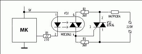
The scheme is simple, I think, further explanation is not necessary. The only retreat, instead limiting resistor placed green LED that will alert the inclusion of an opto-triac.
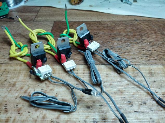
Under the scheme collected, small modules 5 and sockets (picture 3 only):
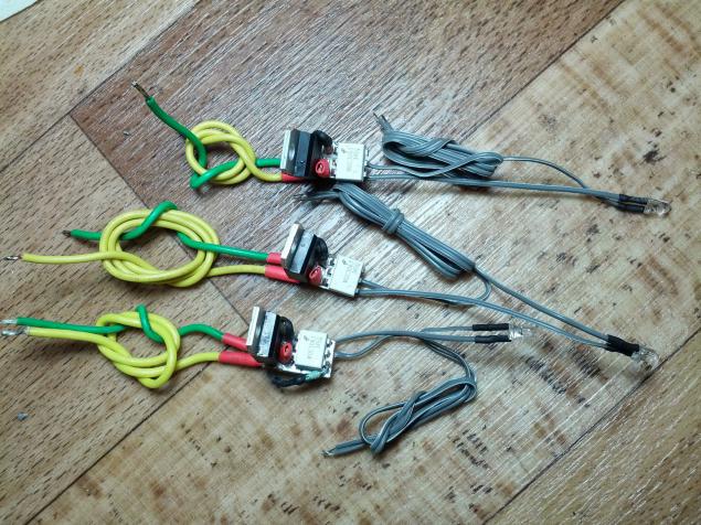
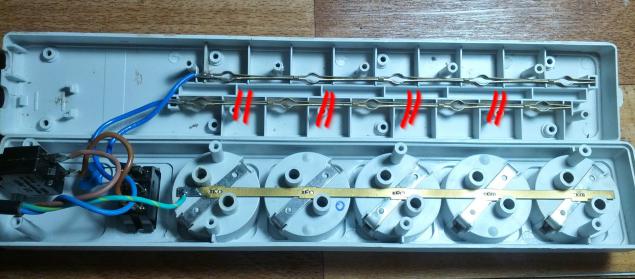
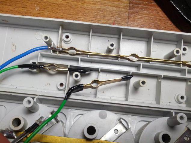
Further, one of the lines in the network filter cut in these places, and cut out the gaps made a jumper to "not fastened" ends that would when the forks are not much unbend.
Control terminals are soldered to pins triac module MCU Module 0.2, 0.1, 0.0, 1.6, 1.5.
5 yellow LEDs soldered to terminals 0.7, 1.0, 1.1, 1.2, 1, 3. the conclusion of 0.5, 0.6 soldered the green and red LEDs for module operation (parsing commands, receiving or sending data).
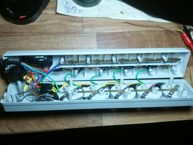
All this stuff packed into the body of the filter network.
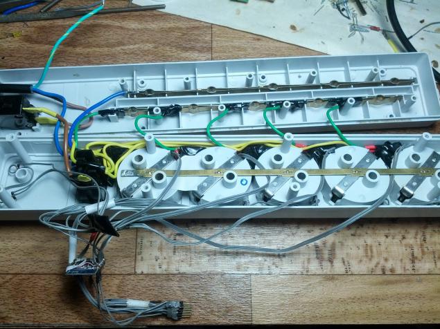
Triac modules fit perfectly into the spaces between the boxes for plugs (pictured them going green and gray wires), the module is installed under the green LEDs (in a pre-drilled holes) on the opposite side from them, set the yellow LEDs.
On the left in the middle of the two ends of the visible status LEDs microns.
Well, in the lower left corner of radio itself is seen hanging from the connector for programming. Wait, where's vaunted microUSB !? At the time of the shooting, microUSB cable, which I had, was too long and the programmer did not see u.
Further, the biggest problem of the whole event: food for the microcontroller. First wanted to make the capacitor food, but you need capacitors and zener diode in the city did not find, and order and wait no longer desire. Decided to use the power supply from charging for some of the phone.
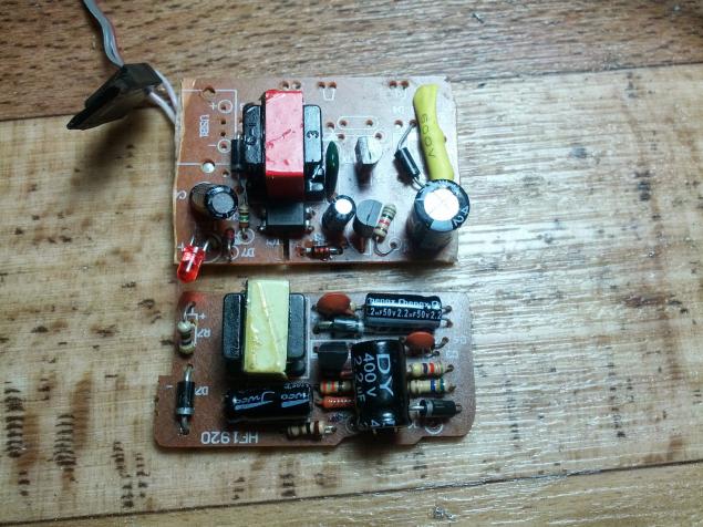
Long suffered from a block that the top (with a red stripe), but it turned out that he had burned optocoupler and zener diode to block extremely strong warming himself. To put such a thing was very dangerous, and I decided to use a block that the bottom (with a yellow stripe), though, and had to leave one of the home devices without power.
It is understood that the condenser option would be much smaller, but there charging galvanic isolation, which allows to deduce the future connector for programming outside of the enclosure.
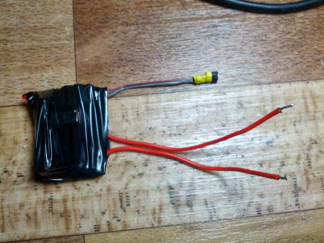
However, the unit is perfectly fit in the filter housing, and the entire structure took the following form:
After assembly in working condition:


functional h4> Unfortunately I can not put the firmware, because it is very confusing. Written with the work of the network with many devices, and in it a bunch of superfluous. If the community would be interested and I finally got an invite then publish everything in the next post. It is noteworthy that no clever algorithm is not there. It all boils down to a simple antsy pins on / off. No Shima and so on. Simple flashing LED (power modules for MC - normal LEDs)
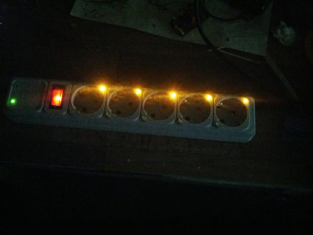
The principle of operation is as follows: when a packet is received from the server, the module determines what should be done with a selected outlet, and enables or disables it. In the off state to the socket against yellow LED lights, turned on the green.
Then I made a very serious mistake, it was necessary to drill holes for the LEDs perpendicular to the holes for the plugs. Since 80% of all power supply units that I found the house, closed or both LEDs, or one.
A little bit about the server h5> The server is the same module nRF24LE1, connected via USB-UART converter to the PC from which the Java application goes through the operation of other devices in the network. Photo below

Conclusion h4> Surge protector is already working for the benefit of my house. Soft yet moist and the meaning of his show and no blush.
Those who are going to repeat this miracle can I send a lightweight version of the firmware and the server, as well as give a couple of tips:
The LEDs should be set perpendicularly, and for particularly wealthy plexiglass, I recommend to make a glowing stroke. Be cool! Self radio module should install in the opposite direction of the voltage input. Interference less, and more places. Use short microUSB It is worth adding persistence function pins during power failure. Himself plan in the new version of firmware do it Special thanks to Associate Professor Yuri Ivanovich Ivanov (Department. Of ACS, SFU) for assistance in the development of other types of capacitor and power supply units. Although in this project do not, I will use them in the following, and be sure to tell you about it, if the community would approve this post.
Expect criticism but rather praise and suggestions to improve the design.
Documentation required h5> Даташит on nRF24LE1
Даташит on BTA16
Datasheet on MOC3063
control circuit power load with a more detailed description of
Source: habrahabr.ru/post/221247/
Tags
See also
15 creative ideas for the comfort of home. After all, life in the comfort of a much more pleasant!
34 items of Power to protect Your home
What materials for the facade of a private house it is better to use
Wooden Wallpaper for a rustic eco home
A house in the land will protect you from many unfavorable influences of energy
How to choose and install shutters to give
In Nigeria looking for unusual ways of dealing with waste
Heating country house WITHOUT gas
Beautiful flight with a rope in the Far East